Tom Mullineaux
RF Engineer

From a cold, dispassionate RF engineering perspective, the automotive radiated test set-up is a strange looking transmit/receive arrangement, with the cable harness of the equipment under test (EUT) suspended above a large copper sheet acting as the transmitter, and a huge antenna close to the chamber floor, and partly in the shadow of the copper sheet, acting as the receiver.
In the guise of a design review1, this article examines the working of the harness/antenna pair design. After the examination it then suggests possible improvements, particularly as regards symmetry of field emanation and thereby symmetry of antenna illumination.

Setting the Scene
To make for an open mind generally, and in an effort to discourage the surfacing of long-held reader prejudices, we shall name parts by their function. Also, to allow the exercise to fit within an article of reasonable length, we will 1) limit the review to the transmitter and receiver parts of the test system, and 2) frame the review with rules and assumptions. We start by renaming the parts of interest.

The Field Emanating Fixture
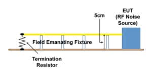
A much simplified layout of the test set-up highlighting the cable harness/copper sheet arrangement is shown in Figures 1(a) and 1(b).
The figures show the 2m long EUT cable harness (in yellow) held 5cm above the copper sheet by insulated pillars. This will be referred to as the Field Emanating Structure (FEF). Auxiliary components such as LISNs and representative loads required by the test are shown to the left of the dotted line. We shall regard these as supporting components only, and concentrate on the parts to the right of the dotted line.
The E-Field Sensor (Figure 2)
It can be argued that the bi-conical antenna positioning and proximity means it is not behaving as an antenna as is commonly understood (no longer a doughnut shaped radiation pattern, etc), and therefore can simply be regarded as an arrangement of vertical conducting rods, unevenly loaded, and unevenly illuminated. So to allow for the widest interpretation, and since we shall be limiting the review to E-Field measurements, we shall call it the E-Field Sensor.
Continuing with the naming by functionality, we will refer to the EUT as a RF Noise Source.
A simplified schematic showing the renamed parts is shown in Figure 3.
Framing the Design Review
As with all well run design reviews, strict rules and assumptions are imposed. These are imperative if solid forward progress is to be made, and if the review meeting is to be completed in a reasonable time.
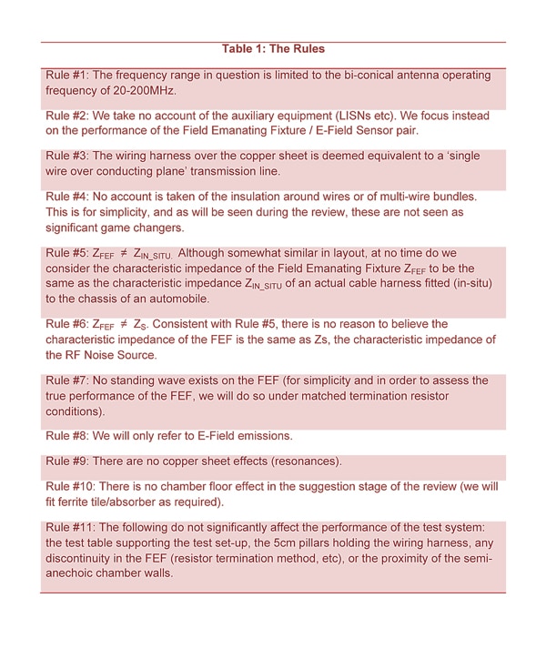
The rules. These are listed in Table 1. The ones that are not self explanatory are referred to within the main body of the article, and so the list needs only a cursory glance before proceeding.
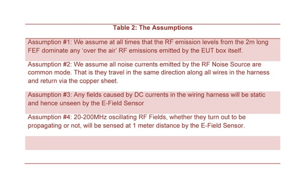
 The assumptions. These are listed in Table 2. Again, these need only a cursory glance at this time.
 With the rules and assumptions in place, we are now in a position to begin the review. For our purposes this is the first review of the design (that is, a review of the designer’s first shot at a solution).
Four steps are taken. First the designer provides a description of the proposed design to the review panel. This is followed by reviewer questions to ensure everyone at the table fully understands the working of the design. Then the reviewers identify, and home in on possible shortfalls in the design. Finally suggestions are made that address any shortfalls.
Although suggestions on possible approaches are given, care is taken to ensure no detailed design work takes place during the review, as this is not the purpose of the meeting. The meeting minutes record the list of development tasks to be completed, and list the data to be gathered ready for presentation at the second review.
THE DESIGN REVIEW
The Test Set-Up Description
The test set-up is designed to measure the level of radiated emissions caused when a subject EUT is connected to a wiring harness. It is assumed that when fitted in the vehicle the vast majority of the emitted fields will emanate from the connected wiring harness as opposed to the EUT itself.
The set-up has two key roles. The first is to emit as RF fields, any RF noise injected onto the harness by the EUT. The second is to measure the strength of the emitted fields.
The emitter role is achieved by using a field emanating fixture (FEF) comprised of 2 meters of the wiring harness suspended over a copper sheet. Measurement is achieved by use of a vertically orientated biconical antenna. The antenna is 1 meter away and centered on the harness.
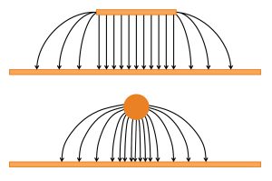
Although somewhat similar to a cable harness fitted to an automobile chassis, the FEF arrangement was in fact borrowed from an aerospace RF emissions test set-up. The cable and sheet act as a transmission line in a similar fashion to a microstrip transmission line. The strong similarity can be seen in Figure 4, where sketches are shown of the E-Field distribution of a microstrip line and of a wire over a conducting plane transmission line. Using one of the free calculators available on-line2 the characteristic impedance of a single 1.5mm diameter wire over the conducting plane was determined as 300 ohms. If correct, this could make sense from a historical perspective as folded dipoles and the old type valve tuners use 300 ohms. However the actual characteristic impedance of the FEF has not been confirmed by measurement.
The sketches in Figure 4 show the E-field concentrated in the gap immediately below the upper conductor (the closer the lines of force, the stronger the field), while fringe fields that weaken with distance emanate to the sides.
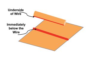
Since the noise currents are at RF frequencies, Mother Nature contrives to make the length of the loop as short as possible (loop area correspondingly as small as can be). This happens when the currents follow a path on the underside of the wire and return immediately below the wire on the surface of the copper sheet, as shown in Figure 5.
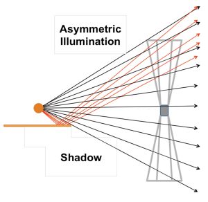
The receiver role is played by a biconical antenna. For these frequencies (20-200MHz), the antenna is necessarily large3. Ideally no fields emanate from the underside of the FEF, so the only illumination of the antenna is from the upper side of the FEF. This makes for unequal illumination as shown in Figure 6.
The asymmetric illumination casts severe doubt on the continued usefulness of calibration data provided with the antenna, but at least as with any field strength transducer, the output will likely increase with increasing field strength. For this reason we will call the antenna an E-Field sensor.
At only 1 meter distance and with the relatively long wavelengths in question the E-Field sensor picks up all fields, propagating and non-propagating.
The present termination resistor is 120 ohms (inherited), and so standing waves will likely exist on the FEF as the RF noise currents bounce to and fro between the mismatch at the termination and the mismatch at the FEF/EUT interface. This creates confusion as to whether the E-Field sensor is measuring fields at points of maximum, minimum, or somewhere in between.
Review Panel Questions Stage
Clarification was given as follows:
The characteristic impedance of the actual cable harness that the EUT will be attached to is not known beforehand since the EUT may be supplied to several auto manufacturers, and even if supplied to only one, the EUT may be installed into many different models.
Even though in some respects the EUT connected to the wiring harness over the copper sheet looks representative of a real installation (except for being held 50mm (originally 2 inches?) above the car chassis), it is in fact a time proven test fixture, representative of an historic aircraft installation set-up.
In the main, the real wiring harness will be attached to the metalwork of the car and so on average the distance between the wires and the metalwork will likely be less than 50mm, with correspondingly lower characteristic impedance.
Although transmission lines tend to be reasonably low loss (otherwise they would not be regarded as transmission lines), the historic FEF is deemed to be leaky enough for reliable field measurement purposes.
The FEF could be made intentionally leakier by for instance increasing the harness height, or by deliberate removal of some of the copper sheet, for instance by cutting out a segment below the center of the harness to increase the fringing field strength.
The source impedance of the RF Noise Source is unknown, and so there could be a bad match between it and the FEF, preventing efficient transfer of the noise signals onto the FEF. It is possible that when the EUT is installed in real life, that the match could improve and efficient transfer of noise onto the harness could take place.
Shortfall Identification Stage
The outcome of the design shortfall identification stage was as follows:
- Although design re-use is encouraged, this only happens where the design is proven and supported with performance data. There seems to be no supporting data with the inherited FEF. To pass this review, data characterizing the proposed FEF must first be obtained.
- The presence of standing waves in an open, locally unshielded set-up such as this does not make for a well behaved RF system. Therefore, to pass this review, all efforts must be made to prevent them.
- The E-Field sensor illumination is asymmetric. In the main, field sensors are intended to be fully immersed in the field they are expected to measure. Without this, in-house calibration data must be obtained.
Review Panel Suggestions


The suggestions put forward for the designer to consider were as follows.
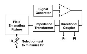
- Characterizing the FEF could be achieved by using a signal generator as the RF Noise Source to provide signals of known frequency and power level, and a single 1.5mm diameter wire can be used as the wiring harness. The signal generator power level can be amplified as necessary. Figure 7 shows the general idea. A 50 Ohm to 300 Ohm transformer is used to assure efficient injection of the test signal. The impedance transformer stages are shown in Figure 8. The transformer uses two very common components in the world of power RF, a 50 Ohm to 75 Ohm transformer followed by a 4:1 transformer. The 4:1 transformer doubles the voltage and halves the current to create four times the impedance of the input impedance as shown in Figure 9. The incident power (Pi) and reflected power (Pr) are monitored using a directional coupler. The resistor value is selected on test to minimize the reflected power and thereby match the load to the FEF characteristic impedance. In fact the designer could stipulate this method to match the wiring harness to the load prior to actual EUT test runs. The designer is now in a position to fully characterize the FEF/E-Field sensor pair.
- Given the FEF is not truly representative of the wiring harness in-situ, then any leaky transmission line could be used as the FEF. For instance, symmetry of the emanated fields could be achieved by using a 300 Ohm 2- wire transmission line. The symmetrical field distribution is shown in Figure 10. The 2- wire could be formed from the wiring harness and a strip of the copper sheet. With this arrangement the E-Field Sensor would be immersed in a symmetric field, especially if the designer insisted the biconical antenna was isolated from the chamber floor (antenna and test FEF raised, floor lined). Food for thought is given in Figure 11, where the idea is that the harness attached to the copper sheet is more representative than the 50mm high harness. However this could create issues of it’s own and so can be dispensed with and the RF Noise Source can be connected directly to the 2-wire FEF. The design engineer is at liberty to experiment using the characterization set-up described above.
- The issue of the propensity of the RF Noise Source to inject noise currents onto a wiring harness of different characteristic impedance is still unresolved. This is crucial and must be resolved for the test-system design to pass this review process.

Conclusion

Although deliberately short on detail, the hope is that readers can see that the application of standard engineering management practices as used daily in commercial enterprises, may be used to generate new ideas to address known weaknesses in current test set-ups. And the incorporation of these ideas might in turn be considered by the standards setting bodies to improve consistency and thereby confidence in product compliance testing.
Notes
- Many people still think of a design review as just a progress check and an opportunity to discuss snags. In fact with the emergence of the new product introduction (NPI) methodology, design reviews are a key component where, as well as ensuring the design is on track, ‘gates’ must be passed before the release of further resource/funding for a project. As a program manager I was very familiar with this methodology, and often wondered how the design of the subject radiated emissions arrangement would fare if put through a formal design review. Hence this article. The intention was to invite input from EMC experts, but they seemed too attached to the existing set-up to look at the design in a dispassionate way, so I decided against this. Although a mock review, the review and outcome is very similar to what I would expect to take place under real commercial conditions.
- http://www.eeweb.com/toolbox/wire-microstrip-impedance. Height above plane 50mm, single wire diameter 1.5mm, substrate dielectric 1
- The bottom of the antenna is close to the fully conducting chamber floor. Meantime the top of the antenna is some distance away from the lined chamber ceiling. This makes for imbalance in the ‘loading’ of the antenna.
AUTHOR NOTE
The article is not a paper requiring copious results or even references, it is an appeal for change. My point is that dyed in the wool EMC engineers with an encyclopedic knowledge of standards, their history, and their implementation are ill suited to push for change, even when they are aware that test set-ups have serious flaws. Independent review using the methods used by the commercial sector is in my view the best way to get through the barricade formed by the experts.
To learn more, visit Interference Technology’s EMC Zone, where Mullineaux blogs regularly.
ABOUT THE AUTHOR
Tom Mullineaux is an RF engineer very experienced in engineering management and technical sales management. He is currently a freelance author and technical writer.
