INTRODUCTION
Modern electronics demand low EMI and EMC conformance, both of which are related to component selection and physical layout in the power supply section of a device. Many more designs are demanding higher power levels alongside high power efficiency, as well as low-noise power supplied to mixed-signal systems. As a result, EMI and EMC challenges are more apparent in many systems, oftentimes leading to re-spins and re-designs.
In this 2-part series, I’ll give an overview on the mechanisms and physical principles that influence the production and propagation of electrical noise. The focus will be on the origination of noise in power supplies and how noise can radiate or conduct to other areas of an electrical system. We will conclude with a discussion on PCB layout for these systems with a focus on suppression of EMI and ensuring compliance in EMC design.
First, let us focus on power regulators, the noise they produce, and how noise is related to circuit design and component selection. Voltage regulators are common in nearly every system that does not use an external power supply, so the selection and design of voltage regulators for power conversion is critical to achieving EMC.
EXAMINING NOISE FROM VOLTAGE REGULATORS
Voltage regulators are the simplest type of power regulator: they accept voltage at one level and convert it to another level while attempting to maximize power efficiency. Voltage regulators come in two forms: switching regulators and linear regulators. Each has different noise characteristics and power conversion capabilities. The trade-off between different types of regulators and power supplies can significantly impact battery life, EMI/EMC compliance, and even the basic operation of a product in development.
Linear Regulators
Linear regulators and LDOs (low dropout regulator) operate by stepping down input voltages to a lower level, and their efficiency depends on the step-down mechanism in the circuit or component. They do not generate EMI directly as they do not rely on switching action to generate and regular a target voltage. For low-power, low-noise requirements, LDOs are a standard option used in modern electronics.
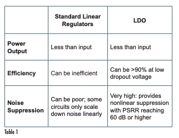
These two types of regulators have simple noise suppression mechanisms, as summarized in the Table 1. For low-noise, high-efficiency power delivery directly to a small circuit, the LDO is clearly superior as long as the input voltage overhead is set correctly. For step-up or step-down operation, as well as high efficiency with high power delivery, designers typically choose switching regulators.

Switching Regulators
LDOs are preferable for low-power digital and analog systems thanks to their low noise power delivery, and they do not transfer excessive EMI at the circuit level thanks to their high PSRR values. However, when higher currents are required, switching regulators are often needed. Switching regulators deliver power through periodic storage and release of energy in a reactive component (inductor and capacitor), which exchanges low-frequency noise for higher frequency ripple at the circuit’s switching frequency.
Today’s switching regulators create conducted and radiated noise, although in most cases, the design and layout of a circuit can be optimized such that certain emissions can be reduced. Conducted emission is generally a larger issue for fixed systems as they tend to require more current, thus the system will generate larger dV/dt and dI/dt events during switching. In contrast, in a portable device running on batteries, there will be no external connections to provide an outlet for conducted noise, thus the device must primarily produce radiated emissions.
Example: DC-DC Converter With Integrated Gate Driver
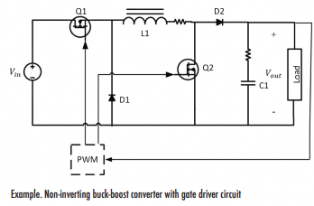
As an example that can be implemented in a real system, take a look at the circuit diagram below. This system uses a control block to modulate the FETs in the design and produce the required power output in a step-down topology. The control circuit is normally available as a gate driver chip that is designed for specific regulator topologies. The external FETs are the switching nodes that generate the high dV/dt and dI/dt action seen elsewhere in the system.
The resistances in series with L1 and C1 are parasitics in these respective components (ESR values), although it should be noted that parasitic inductance is also present in capacitors (ESL values), as well as in component leads/vias, lands, and connecting traces. There are several options to suppress transients in these circuits, depending on the location where the noise originates:
- Input noise filtering is typically applied with capacitors across Vin
- High-frequency ringing at the switching node can be compensated with a snubber circuit •
- Oscillations on the output can be slowed with a small (few Ohms) resistance in series with C1, although this increases the turn-on time
- Oscillations in any output filter must be compensated with small series resistances in the filter circuit
These steps attempt to bring any LC transient response into the critically damped regime.

This regulator has the typical conducted EMI problems that would be observed in any switching regulator. Diode noise (e.g., from D2) is a significant issue in radiated emissions. As the FET switches very fast, diodes can ring in the 50-250 MHz range, and FET transitions create bursts of noise that can be found in radiated emissions measurements.
In this type of regulator, there are two levers that can be used to reduce conducted noise: the cutoff in the LC filter section and the switching frequency. Because the frequency is generally fixed by the internal circuitry of the controller, you’ll have no choice but to tune the output LC circuit to provide ripple reduction and noise reduction by adjusting the inductor.
Typically, designers will opt for a larger inductor in the event they have no control over switching frequency as this directly reduces ripple on the output voltage and current, but it increases size and cost. Depending on the power output in the above converter, it may be preferable to use a simple linear regulator. As long as you don’t mind exchanging some input power for heat, a linear regulator can provide a good solution when you need to convert between low input and low output voltages.
Isolated Topologies
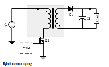
A related converter topology shown below couples power to the output via a transformer (flyback converter). The switching FET modulates the current drawn into the circuit, which then inductively couples to the secondary side of the transformer. Switching action is then rectified in the output stage to produce a DC output with superimposed high frequency ripple.

This converter topology is resilient against ESD propagating from the input to the output. The gap in the transformer and the optocoupler on the feedback line provide physical separation that confines ESD between two sections and ultimately forces it to dissipate into the nearest PE connection. A similar topology is implemented with industrial Ethernet, but the topology is just coupling high speed digital data instead of power. This design also suppresses EMI in the form of dangerous DC currents that might reach any IOs in the system via the ground plane.
However, this design has a new high frequency coupling mechanism through the transformer. Shielded transformers, planar transformers, or another low-capacitance transformer is needed to prevent noise transmission across the primary and secondary sides of the transformer. This is often done by providing a Y-type capacitor across the primary and secondary GND regions, where the capacitance is larger than the winding capacitance of the transformer.
CONCLUSION
So far, we have looked at important examples and concepts used to understand noise propagation in an electronic system. The resulting noise from these designs can produce significant EMI (both conducted and radiated) seen on data lines or analog signals, thus noise must be suppressed at various points in the system. Some options include shielding, filters, proper component selection, and more careful physical layout. The next section will look at the physical mechanisms by which noise will couple around a system and provide some insight into how these noise sources can be addressed.


