This article is intended to provide an understanding of the requirements for qualification of an Absorber Lined Shielded Enclosure (ALSE) for use in the measurement of radiated disturbances in the frequency range of 150 kHz to 2,500 MHz, as described in CISPR 25.
Who is CISPR
In order to provide the technical parameters for verification of these compliance test sites, it would be good to review a few fundamentals of the EMC standard process.
CISPR is the abbreviation for the Comité International Spécial des Perturbations Radioélectriques (English translation: International Special Committee on Radio Interference), which is a part of the International Electrotechnical Commission or IEC. As most of us in the EMC industry know, the IEC is an international organization, including the United States, with committees and subcommittees that focus on the research and development of standards that cover areas like Product Safety, EMC, and Mechanical Hazards. These standards are very often adopted by the European Union in the form of EN (the abbreviation for the French words Norme European or European Standards) and across the world.
CISPR concentrates on drafting standards for controlling electromagnetic interference in electrical and electronic devices that can interfere with broadcasting frequency bands. These bands are regulated worldwide and include TV, AM and FM Radio, as well as ISM, Wi-Fi, Bluetooth and other transmission bands.
Very often IEC and CISPR standards are broken into two categories, Guideline and Product Specific. Product specific standards are used to evaluate and confirm that a product from that product category is compliant with a specific set of requirements. Guideline standards are produced for use by a product committee to use as a basic framework to establish the requirements for Product Specific standards.
What is CISPR 25
CISPR 25 is the standard entitled “Standard for Vehicles, Boats, and Internal Combustion Engines – Radio Disturbance Characteristics-Limits and Methods of Measurement for the Protection of On-Board Receivers“. CISPR 25 Edition 4.0 b:2016 is the most recent published iteration of the standard.
The standard contains “limits.. intended to provide protection for receivers installed in a vehicle from disturbances produced by components/modules in the same vehicle.” The method and limits for a complete vehicle are in Clause 5 and those for components/modules are contained in Clause 6. The disturbances measured are radiated and conducted rf frequency emissions generated from the components of the same vehicle the receiver is installed in, for the purpose of protecting the onboard receivers connected to the power connector provided from the vehicle Harness.
Onboard Receivers are components in the vehicle such as (but not limited to) radio and television broadcast receivers, land mobile radio, radio telephone, amateur and citizens radio, Satellite Navigation (GPS), Wi-Fi, and Bluetooth. They can be original equipment attached to the vehicle wiring harness, or after market add-ons that connect to vehicle on-board power connectors.
The standard does not address unintentional emissions that can be radiated or conducted to off-board receivers outside of the vehicle (such as apply to electric and hybrid vehicles that are connected to AC Mains for charging purposes. These emissions are covered under FCC Part 15 and CISPR 12. Nor does it address onboard receiver immunity to radiated or conducted rf emissions and transient or pulse-type voltage fluctuations. These immunity requirements are covered under the appropriate ISO (i.e. ISO 11452-2) and IEC (61000-4-3) standards.
CISPR 25 Emissions measurements and ISO 11452-2 Immunity requirements are performed in an Absorber Lined Shielded Enclosure (ALSE), as defined in CISPR 25.
Finally, the limits provided by CISPR 25 are guidelines, that can be modified and agreed upon by the vehicle manufacturer and the component supplier.
What is an ALSE
An ALSE as stated in CISPR 25 is “a shielded enclosure with radio frequency-absorbing material on it’s ceiling and walls”. The shielded enclosure provides an environment with ambient electronic noise at least 6 dB below the emissions limits specified in CISPR 25. Most shielded enclosures provide the following minimum shielding effectiveness:
- Magnetic: 55dB @ 10kHz; 95dB @ 200kHz; 100 dB @ 1 MHz
- Electric: 100dB from 15kHz to 100MHz
- Planewave: 100dB from 100MHz to 1GHz
- Microwave: 100dB at 10GHz, 100dB at 18GHz
Shielded enclosures usually require a minimum single leaf door, honeycombed vents to allow airflow while blocking rf radiation, electrical power filters, pipe penetrations, bulkhead panels with connectors, and isolated lighting fixtures. All components allow electrical or physical ingress to the chamber without compromising rf shielding drastically reducing ambient emissions within the chamber, and blocking rf radiation from leaving the enclosure.
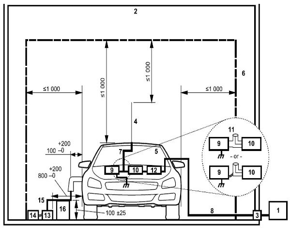
Unfortunately, the metal (Steel, aluminum or copper) walls of the chamber provide numerous reflective surfaces which can cause up to 20dB measurement errors within the chamber. To reduce the reflections within the chamber, hybrid absorber is attached to the walls and ceiling of the chamber. Hybrid absorber is a combination of ferrite tiles backing polyurethane absorber cones. For vehicle testing, no absorber is placed on the floor. For component testing, up to 25mm thick ferrite tile can be added to the floor only if the performance of the ALSE still meets the requirements of Annex J of CISPR 25. Annex J is the section of CISPR 25 that defines validation procedures for the ALSE, and we will review that section in detail. The minimum size of the chamber dimensions is determined by ensuring a 1m separation between either the vehicle or EUT, the receive antenna, and the tips of the surrounding absorber material.
The ALSE is cleared of all items not pertinent to the test to remove reflection sources like unnecessary equipment, cable racks, storage cabinets, office furniture and the like.
Figure 1
Defined Test Equipment
Antennas for CISPR 25 testing are defined in the standard, specified as 50 Ω systems and are as follows for different frequency ranges:
| Frequency Range (MHz) | Antenna |
| 0.15 to 30 | 1m vertical monopole antenna |
| 30 to 300 | A biconical antenna |
| 200 to 1,000 | A log periodic antenna |
| 1,000 to 2,500 | A horn or log periodic (suitable for the range) antenna |
Another critical object for testing in a CISPR 25 chamber is the test table or test bench. The bench shall be composed of rf non reflective material, with a reference ground plane (RGP) composed of minimum 0.5 mm thick copper, brass, bronze, or galvanized steel sheet metal bonded to the top of the bench. The minimum size of the RGP atop the bench shall be 1m wide and 2m (or underneath the entire test equipment plus 200mm, which ever is larger) in length. The height of the RGP shall be 900 (+/- 100mm) above the floor. The test table shall be bonded to the ALSE Ground by a series of straps with a maximum length to width ratio of 7:1, and a maximum separation from one ground strap edge to the adjacent ground strap edge of 300mm. AS a result of this bonding scheme, the bond between the table surface and the ALSE Ground shal be less than or equal to 2.5mΩ.
EUT/Table Setup
In order to discuss the ALSE qualification testing and verification, it is helpful to review the test setup for normal component testing within the ALSE.
The EUT is placed upon a non conductive, low relative permittivity material 50 (± 5mm) thick on the RGP. The EUT is not grounded to the reference plane unless intended to simulate actual vehicle configuration. The side of the EUT is located 200mm (± 10mm) from the front edge of the Reference Ground Plane (RGP). A test harness is attached between the EUT and load simulator, including power lines, and does not exceed 2m in length. The Test Harness is also placed upon a non conductive, low permittivity material 50 (± 5mm) above the RGP.
Figure 2
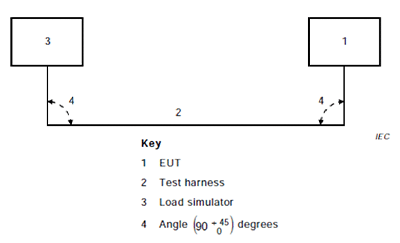
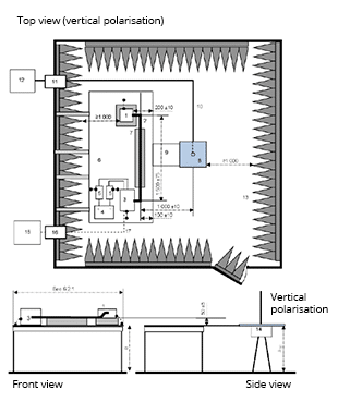
The test harness parallel to the front of the RGP is 1.5m in length, spaced 100mm (±10 mm) from the front edge of the RGP. The antenna is located 1m from the long segment of the test harness, with the Phase center of the antenna in line with the center of the test harness for frequencies below 1GHz, and the center of the EUT above 1 GHz. The monopole counterpoise is bonded to the RGP. See Figure 3 for an illustration of the test setup for a monopole antenna.
Figure 3
Verifying the Chamber using the Reference Site Method
Annex J of CISPR 25 describes 2 individual methods to qualify an ALSE for testing to CISPR 25. These are provided to establish repeatability between similarly constructed chambers. They are intended for component testing per 6.5 and therefore employ a RGP. Both methods (Reference Site Method, and the Long Wire antenna method) utilize a Reference ground plane as described in the test section above, with some deviations in size and as to how the RGP is grounded to the ALSE Ground (details to follow). Either method will satisfy the verification process.
The first method is the Reference Site Method (RSM).
The reference site method compares reference Measurements (RM) taken in an Oats or similar qualified emission site and compares them with measurements taken with a normal setup inside the ALSE to be qualified. The deviation between the reference measurements from the verified OATS Site and the ALSE measurements must be within a defined tolerance.
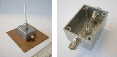
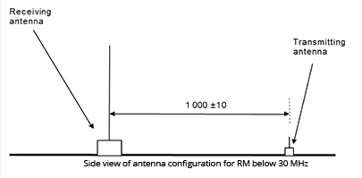
When conducting the RSM, the same receive antennas described above are used for the reference measurements (OATS) and the ALSE verification measurements. However, the transmit antennas are a short passive monopole in a vertical position for under 30 MHz testing (See Figure 4) and a small biconical or shortened dipole placed in the normally EUT Harness position for greater than 30 MHz to 1 GHz. The monopole has the following parameters:
- <30 MHZ short passive monopole in vertical position
- Height including drive unit, <500mm
- Monopole diameter, 10mm
- Optional top loading disc diameter, 120mm
- 3rd port is unterminated
Figure 4
Transmission Coefficient (CT) Reference Site Measurements
Very similar to NSA testing in CISPR 16-1-4, the procedure for obtaining the Transmission Coefficient Measurement (CT) at each frequency is done by taking a direct conducted measurement (M0) and a radiated measurement (MA) and comparing the two.
CT = MA – M0
The Direct conducted measurement (M0) is taken by connecting transmit and receive antenna cables together. An initial measurement is made with the output power set. Then to confirm no overload condition in the measurement system, the power is dropped 10 dB and measured again. The power level then remains the same across the frequency spectrum. For the radiated Measurement (MA) an initial noise floor measurement is also taken with the transmit antenna disconnected. All subsequent antenna measurements for CT calculation must be at least 10 dB above the noise floor measurement.
CT (Reference Site Data) is broken into 2 measurements and uses different antennas and test setups below and above 30 MHz. To start the process, we take conducted Measurements (MO) at the reference site across the spectrum from 250 kHz to 1,000 MHz, following the step size defined in CISPR 25 below:
- Frequency Step size:
- Same used for ALSE and Reference measurements
- 481 frequencies used
- 150 frequencies from 250 kHz to 29.95 MHz (200 kHz step size)
- 170 frequencies from 30 MHz to 199 MHz (1 MHZ step size)
- 161 frequencies from 200 MHz to 1,000 MHz (5 MHz step size)
This gives us 481 conducted measurements from 250 kHz to 1,000 MHz.
We then repeat these first sequence of 150 frequencies and step sizes for the Radiated Reference portion below and up to 30 MHz. For this setup, the transmit and receive antennas are placed upon the floor of the OATS or similar verified chamber with the transmit antenna described in Figure 4 and our 1m monopole receive antenna, 1m apart, and a measurement is taken for each frequency. For all Transmit and receive antenna configurations used, ferrites are added to the transmit and receive antenna cables with values of 50 Ohm at 25 MHz, 110 Ohm at 100 MHz, and placed every 20cm on the cables. All transmit cables are routed toward the back of the RGP.
See Figure 5 for Setup.
With this data we calculate CT REFERENCE<30 MHz = MA-MO reference site < 30 MHz. Since this is a vertical Monopole measurement, there is no horizontal data less than 30 MHz.
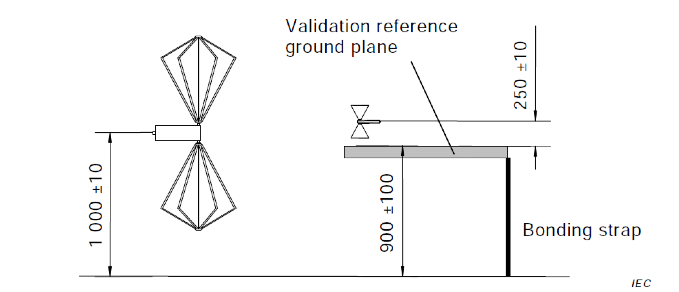
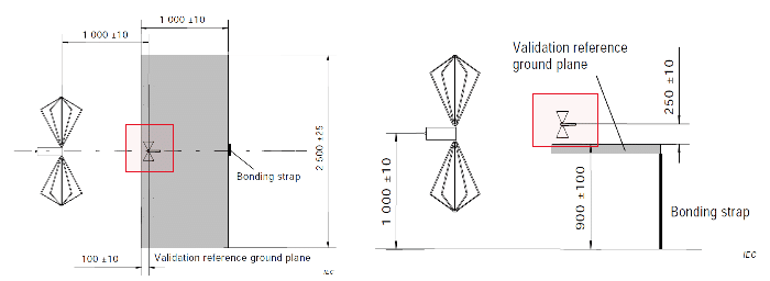
We then take our radiated (Reference) measurements for greater than 30 MHz using the step size and frequencies listed above and with the various receive antennas. These measurements are taken with a similar setup to the EUT Tests we described before, but with some variations. The testing is still performed on the verified Reference Test Site (OATS, Weather Protected OATS, SAC). The elevated RGP (now our validation RGP) is required for testing from 30 MHz-1 GHz. The RGP is 2.5m x 1m (0.5m longer than EUT Test bench setup). The Validation RGP is bonded to the Site Ground Plane by a single strap 100mm (+11, -0mm) wide centered on the rear length of the Validation RGP. See Figure 6 and Figure 7 for an illustration of the validation RGP Setup for Horizontal and Vertical Reference Site Measurements between 30 MHz and 1 GHz.
Figure 6
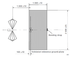
Figure 7
Once again, we calculate the CT measurement data for the reference site using
CT Reference > 30 MHz= MA Reference > 30 MHz – M0 Reference > 30 MHz
For both Vertical and Horizontal Polarization. We now have all reference site data from 250 kHz to 1000 MHz.
It is then time to take the ALSE to be qualified data below and above 30 MHz.
Transmission Coefficient (CT) ALSE Site Measurements
For ALSE Transmission Coefficient measurements above and below 30 MHz, the Bench size and setup for EUT Testing is used. That means the same size RGP, the same number and size of bonding straps, and the same receive antennas are used as with normal EUT Testing. The Monopole antenna Counterpoise is bonded to the RGP. The same transmit antennas as the reference site measurements for below and above 30 MHz are located where the test harness would normally go. Figure 8 shows the test setup for the ALSE measurements below 30 MHz. Figure 9 Shows the transmit antenna placement and setup for ≥ 30 MHz.
Figure 8
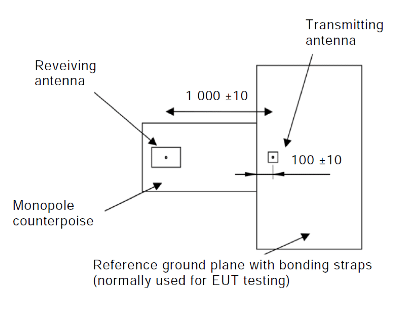
Figure 9
Once again, CT is calculated for the ALSE Measurements ≤ 30 MHz (vertical polarity only) and >30 MHz (vertical and horizontal polarity).
CT ALSE≤30 MHz= MA ALSE<30 MHz – M0 ALSE≤30 MHz
CT ALSE≥30 MHz= MA ALSE≥30 MHz – M0 ALSE≥30 MHz
Deviation (Δ )in Transmission Coefficient (CT) and Percent of In Tolerance Data (%IT)
Once all data is taken, we calculate the Deviation between the reference site and the ALSE for < 30 MHz
![]()
And count the number of data points that are within 6dB. This gives us our Δ <30 MHz.
Then we calculate the Deviation for >30MHz for both Horizontal and Vertical antenna positions.

And once again count the number of data points within 6dB
Having our Δ calculations for ≤ 30 MHz and >30 MHz Horizontal and >30 MHz Vertical, we are able to calculate the % in Tolerance Calculation.
- First calculate %IT for each Data Set
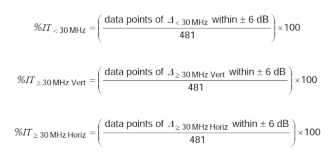
- Next, Find the minimum %IT data points for ≥ 30 MHz
![]()
- Finally, calculate total percentage of Data Points within the +/- 6dB requirement over entire frequency range of 150 kHz to 1000 MHz
![]()
The ALSE and it’s installation is compliant with the requirements of this validation method if:
Total %IT 150 kHz to 1000 MHz Ref Method ≥ 90%
NOTE: the Total %IT can be greater than 100.
Long Wire Antenna Measurement Test
The alternative method for qualifying an ALSE to CISPR 25 is the Long Wire Antenna Test. This fixture is defined in CISPR 25 as a:
- Brass rod (4 ± 0.2 mm) diameter
- Height of (50 ± 2 mm) between ground plane and closest point of rod
- Held by 2 metallic sheet angles separated by (500 ± 5 mm)
- Type N connectors integrated in angles as rod support
- Rod located (100 ± 2 mm) from ground reference edge and at center of cabling harness used for EUT Testing
- Metallic sheet angles bonded to GRP by screws or plastic clamps DC resistance ≤ 2.5 mΩ
- Load end of radiator terminated with (50 ± 7.5) Ω RF load (max VSWR 1.2:1 from 150 kHz to 1000 MHZ) through type N connector mounted in metallic sheet angle
- RF feed end of radiator connected to 10 dB, 50 Ω attenuator (max VSWR 1.2:1 from 150 kHz to 1000 MHZ) through type N connector mounted in other metallic sheet angle
- RF feed cable connects RF source to 10 dB, 50 Ω attenuator
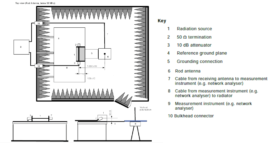
Figure 10 shows the support brackets. Figure 11 and 12 shows the Transmit antenna fixture.
Figure 10
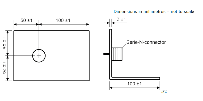
Figure 11

Figure 12
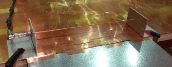
As in the reference site method, receive antennas used during EUT testing are used to perform this test. Once again transmitted power is lowered 10 dB and a repeat measurement is taken to determine no overload of the receive section. The same Physical layout, RGP size an bonding of the table as in EUT testing is used (Multiple Bonds). The monopole antenna counterpoise is connected to the table (RGP). The Long Wire Transmitting antenna is placed on the RGP at the center of the normal location of the test harness. Figure 13 shows the test setup for the monopole antenna portion of the Long Wire Test.
Figure 13
Long Wire Test Procedure
The same frequency step size and measurement frequencies are used as in the reference test method for the ALSE Testing. Conducted Measurements (MO) and Transmit and Receive antenna Tests (MA) are made. Transmit Signal Generator is set to 1Vrms for both measurements.
- Equivalent field Strength (Eeq)= 120 dB(uV) + (MA – M0) + k AF
- k AF is antenna factor of receive antenna in dB(1/m)
- Below and at 30 MHz, measurements are made in Vertical position only. Above 30 MHz, measurements are made for both Horizontal and vertical polarities of the receive antenna and Equivalent Field Strength is calculated. During all tests, the long wire antenna is used as the transmit antenna. For each frequency, Eeq,max is derived as maximum of either Eeq, horiz and Eeq, vert.
However, instead of taking reference site measurements, the data from the reference site measurement is replaced with table J in CISPR 25 for the 3 frequency ranges and the Equivalent Field Strength (Eeq) is calculated.
Table J1 in Appendix J of CISPR 25 lists all frequencies Eeq,max,ref in dB(uV/m) for calculations

Deviation of ALSE measurements from the values in Table J are calculated using the following:
- For each frequency
- Δ Long wire Method = Eeq,max – Eeq, max,ref Δ in dB
- Where:
- Eeq,max is the maximum field measured at a particular frequency (maximum of both horizontal and vertical polarizations, where applicable)
- Eeq,max,ref is the modelled reference field as shown in table J1 at the same frequency as Eeq,max
To calculate the %IT (Total percentage of data points within 6dB over the entire frequency range, we use the following formula:

- data points 150 kHz to 1000MHz whereΔ Long wire Method is within ±6dB is the number of frequencies where Δ Long wire Method is within ±6dB as evaluated above
The ALSE and its installation is compliant with the requirements of this validation method if
- Total %IT 150 kHz to 1000 MHz Long Wire Method ≥ 90%
Possible causes for exceeding site acceptability limits
CISPR 25 recommends that the following items be rechecked if the site deviation
- Measurement procedure
- Antenna factors accuracy
- Drift in the signal source
- Accuracy of the receiver or spectrum analyzer input attenuator
- Measurement device readings
If no errors are found, it is likely that the site is at fault and should be investigated. Figure 14 shows examples of typical ALSE influence parameters over the 10 MHz to 100 GHz range.
Figure 14
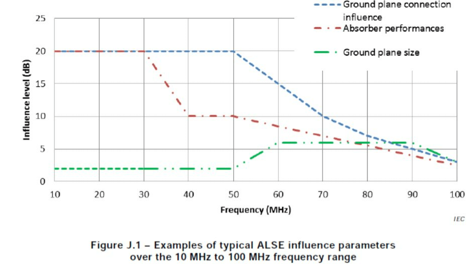
Key items recommended by the standard include:
- Reference Ground Plane
- RGP bonding straps
- Absorber performance
Modification of one or more should help to improve ALSE performance. In some cases, <30 MHz, resonances may be observed. To reduce the influence of resonance, you can:
- Apply foam block absorber between the bottom of the receive antenna and the floor
- Bond the counterpoise of the receive antenna with additional grounding straps to the florr on the opposite side from the connection to the RGP from the connected side of the RGP


