Introduction:
MIL-STD-461G was issued in December 2015 incorporating many changes throughout the document prompting user questions or interpretations. Laboratory situations arise where the generic guidance requires specific situational decisions and the most common tests such as RE102 are included. The user quickly realizes that the given direction does not make sense for a special case and sees a need to deviate from the standard.
Normally the deviations are documented in the test procedure and procedure approval supports the alternate test approach. The absence of an approved test procedure would necessitate documenting the deviations in the test report and hope that the approving authority agrees with the approach. This situation becomes more difficult when device qualification is a self-funded development, and a clear approval line is not defined.
The standard committee does a good job of informing the reader in the appendix on why certain elements are present and how those elements relate to the test goals and real-world situations. However, it would be impossible to deals with every potential situation.
This article looks at RE102 changes and discusses the associated implications. Answers are not always clear-cut, but the discussion provides elements to consider in arriving at your approach. Note that some implications considered are outside the RE102 section of the standard.
Paragraph 5.18.1 Applicability (Transmit Mode):
In MIL-STD-461F paragraph 5.17.1 the radiated emission applicability included antennas “designed to be permanently mounted to EUTs (receivers and transmitters in standby mode),” Revision “G” paragraph 5.18.1 removes the direction to test in the standby mode. In both revisions, compliance is not required at the transmitter fundamental frequencies and the occupied bandwidth for permanently mounted antennas.
This seemingly minor change has some far-reaching implications. Some interpret this to simply mean an operation change to activate the transmitters and do the test omitting the frequency range of the transmission. Others interpret this to mean testing in two different modes: 1) receive/standby and 2) transmit effectively doubling the testing. Let us not forget that testing at three frequencies per tuning band applies for tunable equipment.
Was the intention to test in transmit only or to add the transmit mode of operation? Let us consider the RE102 testing scenario for a rather simple radio transceiver Equipment Under Test (EUT) operating with VHF-AM (30 MHz – 225 MHz) and UHF-AM/FM (225 MHz – 500 MHz) with a fixed frequency (13.56 MHz) RFID transceiver wireless capability.
- Standby/receive, EUT at 31 MHz, AM
- Standby/receive, EUT at 88 MHz, AM
- Standby/receive, EUT at 220 MHz, AM
- Standby/receive, EUT at 235 MHz, AM
- Standby/receive, EUT at 370 MHz, AM
- Standby/receive, EUT at 495 MHz, AM
- Standby/receive, EUT at 235 MHz, FM
- Standby/receive, EUT at 370 MHz, FM
- Standby/receive, EUT at 495 MHz, FM
Then repeat those tests in the transmit mode for a total of 18 operational mode tests with vertical and horizontal antenna polarizations.
Note that compliance at the fundamental frequency and occupied bandwidth is not required for transmit mode. What about harmonics of the transmit frequency? The CE106/RE103 requirements call for 80 dB suppression of harmonics and spurious emissions with less suppression for the 2nd and 3rd harmonics.
Placing some hypothetical numbers into this one of the test modes reveals a high-level signal arriving at the detection system. Assume a 1-watt effective radiated power at 235 MHz, the detected transmission would be as high as 120 dBμV/m with the 2nd and 3rd harmonics allowed to be as high as 100 dBμV/m and other harmonics up to 40 dBμV/m as specified for RE103.
Figure 1 shows emission levels from a “compliant” device with Army ground applications where the transmitter is active at 235 MHz. Since 235 MHz and the associated occupied bandwidth is exempt from the compliance requirement, testing in that frequency range could be omitted. However, the signal is being emitted at 120 dBμV/m as indicated on the graph. This indicates that the receiver system needs at least 90 dB of dynamic range to allow the transmit signal and compliant emissions to be detected at or below the RE102 limit. The high-level transmit signal tends to overload the receiver and attenuation is used to prevent overloading. This added attenuation reduces the sensitivity of the receiver so low-level emissions are masked by the increased receiver noise. To improve the sensitivity the transmit signal needs attenuation without applying attenuation to nearby frequencies. Notch filters (see Figure 2) are normally used to reduce the transmit signal amplitude but fitting a notch filter to the occupied bandwidth is difficult which leaves a range of reduced sensitivity near the transmit frequency but outside the occupied bandwidth. Also note that with multiple EUT operating frequencies the band rejection notch will need to align with each operating frequency.
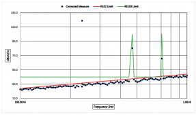
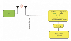
Figure 1 also shows high-level emissions for the 2nd and 3rd harmonics which would exceed the RE102 limit. If we consider RE102 requirements alone, these harmonic emissions would be non-compliant. These harmonic emissions would be compliant if we compared the emission with an RE103 limit adjusted for allowing harmonics as indicated in Figure 1. It is feasible that the 2nd and 3rd harmonics could comply with the RE102 limit but requiring compliance as presently stated (or not stated) in the standard places an additional burden on the transmit function.
Some implications remain if the antenna is not permanently mounted. The exemption for compliance at the transmitter frequency is no longer supported. The antenna cable is classified as an interconnecting cable and as such should be terminated into the normal load. If the cable provided 60-80 dB of shielding effectiveness, cable radiated emissions could easily exceed the RE102 limit. If the transmitter power is high, the cable radiation could also force the need for notch filtering at the detection system to prevent overloads as discussed above. If an allowance for this emission is not provided, we force the installation to add control measures for this cable.
Paragraph 5.18.1 Applicability (Test Frequencies)
In MIL-STD-461F paragraph 5.17.1 the radiated emission applicability included a note requiring testing up to the greater of 1 GHz or 10 times the highest intentionally generated frequency up to 18 GHz. That note disappeared in revision “G” implying testing to 18 GHz for all cases. The premise for stopping at 1 GHz for low-speed devices was based on a long history that these types of devices did not produce high-frequency emissions of significance meaning that if the unit was compliant below 1 GHz then compliance would be maintained. That premise still holds true, so why make the change. Testing above 1 GHz reveals that below limit noise not related to EUT operation is normally all that is measured.
Discussion with a person attending the committee meeting adopting revision “G” revealed that testing to 18 GHz had minimal impact on testing, so there was no reason to avoid testing to 18 GHz.
What is the minimal impact? Time comes to mind as an impact. If a scanning receiver is used, the test time between 1 GHz and 18 GHz for each sweep is about 20-minutes if everything goes smoothly and minimum dwell time applies. Assuming the simple radio transceiver we defined above and only one detection system antenna position the 1-18 GHz testing would take about 6-hours. If the EUT size demands additional antenna positions, we should provide for an impact of about a day per antenna position or possibly 2-positions per day, if we are optimistic. I recently worked a test project with a need for seven antenna positions, and all test sweeps in the 1-18 GHz range did not detect any EUT related emissions. The impact was a full day in the lab along with the support personnel was used to complete this portion of the testing. The cost of that day had to amortize on a sale for four devices.
The impact is greatly reduced if a real-time spectrum analyzer (RSA) is used because the time for a sweep from 1 – 18 GHz takes a minute or so with the normal bandwidths and associated processing time. The impact for the seven antenna positions could have been in the order of a half-hour. This amount of time savings tends to justify investment into an RSA especially if large test articles are frequently encountered.
Paragraph 5.18.2 Limits:
Although not changed by revision ”G” I want to bring up an item that has caused a bit of confusion. Often multiple services and applications may be applicable and the RE102 limits are not the same for each application. Normally the most restrictive limit is selected and if compliant then all applications are classified as compliant.
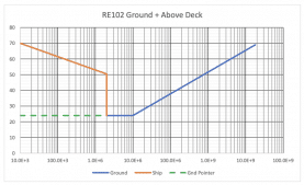
Certain scenarios can demand that a tailored limit be created. For example, a device requiring compliance with Army Ground applications could also apply to Marine Corps where shipboard above deck application limits is appropriate during deployments. Ground applications call for testing between 2 MHz and 18 GHz as shown in Figure 3 and the ship applications test frequency range of 10 kHz to 18 GHz. In MIL-STD-461G, the ground limit adds a dashed line which some have interpreted to be a limit extension where the 24 dBμV/m limit is extended to the combined start frequency, The dashed line was intended to show that the limit was 24 dBμV/m with the number at the chart edge (this pointer is shown in Figure 3), If one keeps the 24 dBμV/m limit, compliance would not be reasonable because of uncontrollable ambient conditions. The proper way to combine the limits is indicated in Figure 3 with the ship limit applicable between 10 kHz and 2 MHz and then the ground limit applies between 2 MHz and 18 GHz. This combination provides the most restrictive limit for merging the two applications.
Paragraph 5.18.3.3.c, (2) Antenna Positioning:
The test setup boundary is not the same as the ground plane surface. The test setup boundary is defined by the EUT and associated cables. This boundary should be used for locating the detection system antenna at the prescribed 1-meter distance.
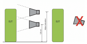
Antenna elevation is set to 120 cm above the floor ground plane to physical points defined in the antenna position diagrams. For the double ridge guide antennas, a note has been added to support antenna elevation adjustments. This reminds us that the elevation is adjusted to provide for emissions measurements within the antenna beamwidth – do not tilt the antenna to provide beamwidth coverage as indicated in Figure 4.
Paragraph 5.18.3.4, Procedures:
Sub paragraph a. calls for verification that ambient requirements specified in 4.3.4 are met and take plots of the ambient when required. This ambient is the test configuration ambient with support equipment operating and the EUT de-energized. A resistive load drawing the same rated current as the EUT is substituted for the EUT when measuring the power line ambient. Paragraph 4.3.4 states “When tests are performed in a shielded enclosure and the EUT is in compliance with required limits, the ambient profile need not be recorded in the EMITR.”.
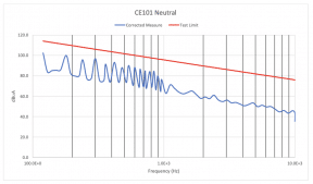
Why are we performing an ambient set of measurements before we determine if the EUT is compliant? Why do we struggle with attaining an ambient at least 6 dB below the limit if the EUT is compliant? We do it because the standard requires ambient measurements. This seems to be a waste of time since the data is not used. Consider the test results shown in Figure 5. The plot shows that the EUT is compliant with the applicable limit therefore an ambient plot would also show compliance. Following the standard, we would be obligated to locate a resistive load to match the EUT load, complete an ambient scan and then disregard the data. And this scenario crosses into the radiated measurements where more data would be disregarded. I try to avoid this time waste by including in the test procedure that ambient measurements are accomplished if the EUT demonstrates non-compliance. Upon approval of the procedure, the tailoring of the test is agreeable.
While we are on the subject, what is the “same rated current as the EUT”? MIL-STD-461G, paragraph 4.3.1 provides several measurement tolerances but current is not one of them. Is it safe to assume that the tolerance is ±5% because resistance and current are directly linked? State a tolerance in the test procedure to avoid making assumptions that a reviewer may not accept.
Why use rated current instead of the test configuration current? It is a common practice that “rated” is higher than actual demand. The rating provides guidance for circuit capacity and the associated electrical safety measures of the device such as making sure that the wiring has sufficient ampacity. Testing CE101 may provide for limit relaxation based on the current without using “rated:” as a qualifier. Typically, the EUT current in the test configuration is measured (the test report DID specify placing this measurement in the report) and that measurement serves as the basis for relaxing the limit. If an EUT rated for 3-amperes would qualify for a 9.5 dB relaxation but an actual draw of 1.5-amperes would only support a relaxation of 3.5 dB. The test procedure should clarify so assumptions are avoided.
Sub-paragraph c. incudes several specified frequencies instead of the prior instruction to use the highest test frequency of each antenna. The specified frequencies avoid using a frequency that would be on a graph grid line so the amplitude visibility is not obscured. Additional frequencies are to be added if changes to the measurement system path hardware is changed such as changing a pre-amplifier.
Sub-paragraph c. (3) maintains that commercial calibration jigs or injection networks shall not be used. This issue relates to stray capacitance causes the nominally 10 pF capacitor to be outside the allowed tolerance for many jigs. When using a “home-made” 10 pF (or value specified by the antenna manufacturer) construct the attachment to minimize stray parasitic capacitance.
Summary:
RE102 gets a lot of focus since it is frequently accomplished early in the test program because it provides a lot of information without using potentially destructive test methods. Remember to pay attention to the test configuration – minor variances in the layout prompt potentially significant variances in the measurements.
Hopefully, you will find this information useful and I welcome questions. If you have a topic associated with EMC that you would like to have reviewed, let me know and I will try to place it in the queue for future articles.
