INTRODUCTION
Digitization and the spread of pervasive computing is at the forefront of the technology innovation that will shape our modern universe and it is already manifesting itself in IoT, 5G and autonomous vehicle spaces, to name just a few areas. As this spread of technology increases, so does the need to regulate it – in terms of how these devices and systems communicate (allocation of frequency spectrum, bandwidth, etc.), but also with respect to how they radiate unintended emissions and respond to interference. As more regulations and stricter requirements are put in place, electromagnetic compatibility (EMC) is becoming more relevant than ever before. Technology coexistence is of the essence.
SIMULATION AS A DRIVER IN THE EMC PROCESS
Typically, EMC testing is performed towards the end of product or system development cycle. One of the biggest risks is that an unexpected problem is uncovered during the testing phase, forcing a design modification and a delay in the product release until certification has been achieved. This raises the question: why wait until the end of the development cycle? EMC measurements are either carried out on-site or using certified test laboratories – and in many cases these measurements can be both time consuming and expensive.
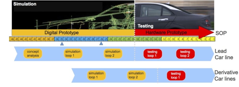
And here within lies the true value of incorporating electromagnetic simulation into the EMC process. Simulation can be applied throughout the product development cycle, making it possible to compare different concepts and design variations – not only from a performance perspective, but also with respect to EMC ability. As the product evolves, EMC aspects can be analyzed, e.g. comparing different component locations in a system or optimizing cable routing paths to minimize coupling. Rather than considering EMC as an afterthought, this approach will help predict and mitigate potential EMC issues much earlier in the process. Furthermore, simulations can give in-depth insight into the root cause of EMC issues (for example through visualization of the near-fields and surface currents) and in the development of more robust solutions.
CHALLENGES IN EMC SIMULATION
Of course, EMC simulation is not without its own set of challenges. Typically, EMC problems must be analyzed over a broad frequency range, often deal with multidimensional geometry, and finally contain multilevel complexity, e.g. components, connectors, cables, housing, antennas, radomes and the platform where everything is integrated. Each of these aspects implies certain numerical challenges, which must be addressed accordingly. For example, FEKO is a comprehensive electromagnetic simulation platform for antenna design, placement and EMC analysis. It has been developed with the goal of addressing the abovementioned simulation challenges. In short, several different solvers are available, offering true hybridization, model decomposition and special formulations for cables – all of which is towards providing seamless workflows for EMC analysis. Validation is also extremely important, and in[1] FEKO was validated for a variety of typical EMC applications.
The following section includes several industrial case studies where we will discuss some of these typical EMC challenges in more detail and describe how simulation was applied to solve them.
CASE STUDIES
Radiated Emissions & Immunity: In the automotive industry, two types of EMC cases are primarily of interest: radiated emission and immunity tests. Radiated emission tests (component and vehicle level) deal with ensuring the emitted fields are below the required levels in the specified frequency bands.
Radiated Emissions – Figure 2 shows simulations of the 10m radiated emissions for an electronic control unit (ECU) in a vehicle. Note that the geometric information of the ECU could not be disclosed by the supplier in order to protect their intellectual property. In this case, measurements were made for the ECU, which were imported into FEKO as an equivalent source and used for the vehicle level simulations. The figure shows that for most frequencies the ECU emissions from the vehicle are below the required level except between 500-600MHz where only one polarization meets the requirement. In addition to comparing the emission levels for different ECU locations in the vehicle, the coupling to a cable and a DAB windscreen (operating at 200MHz) were also considered.
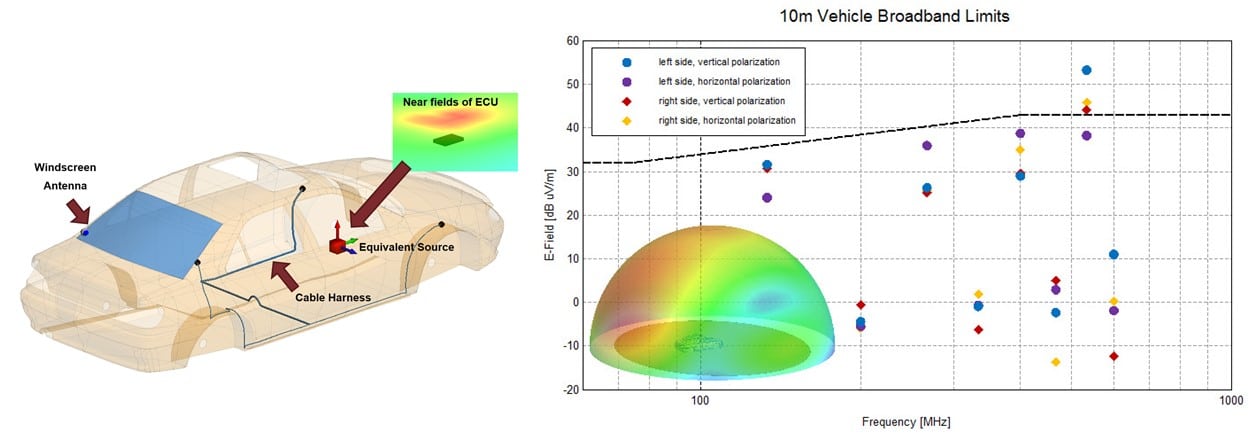
Radiated emissions are also specifically of interest in the context of electric and hybrid electric vehicles due to the high-power cables. In this case, radiation of harmonics generated by switching circuits in the IGBTs and DC-DC converters can increase the emissions. FEKO can be used to simulate how different cable path routing and cable shielding configurations can reduce these emissions.
Radiated Immunity – Radiated immunity involves ensuring that the vehicle sub-systems continue to operate with expected behavior under the influence of external electromagnetic disturbances, for example, testing that the airbags still deploy correctly when the vehicle is radiated by high intensity fields. In these cases, simulation can help to determine the optimum locations for a sensitive ECU or best routing cable paths.
As an example of real use case, FEKO is used for the simulation of the automotive immunity tests according to the ISO 11451-2 substitution method[2]. In Figure 3, one can see the model of a sedan in FEKO and the considered simulation cases.
The comparison between measurements and FEKO simulations for one of the considered positions, i.e. P10, and when considering the transmitting antenna polarized vertically and placed in front of the vehicle (Front – Vertical). In the measurements two log-periodic antennas were used; the first one from 20 MHz to 200 MHz, and the second from 200 MHz to 1 GHz. In the simulation, a set of six dipoles represented each antenna, and the size of the dipoles was changed depending on the frequency band.
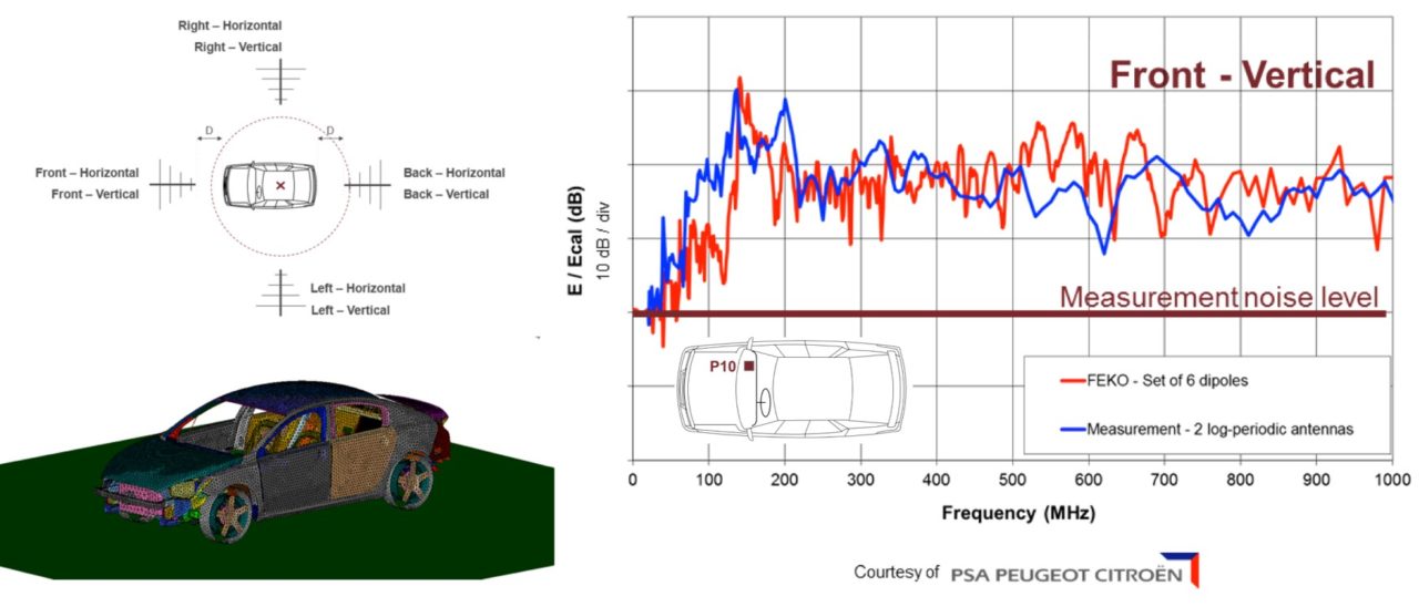
To obtain comparative results, the simulation and measurement data were normalized with their calibration values, respectively (E/Ecal). The comparative study between simulations and measurements shows a nice agreement up to 450 MHz, and for higher frequencies, there are some differences between simulation and measurement results caused by the effect of non-metallic parts of the structure that are not represented in the simulation model.
HIRF & LIGHTNING ANALYSIS:
While similar arguments for simulation can be used for aerospace applications, the physical size of the airplanes means that the cost, complexity and time needed for measurement is significantly higher. All of these factors further strengthen the idea of a simulation based EMC approach.
HIRF – In aerospace EMC, one area of great importance is understanding the field effects in and around the plane when it is exposed to an external field source – here the source could include high power transmitters (as covered by High Intensity Radiated Fields (HIRF)), or a direct lightning strike on a plane. Typically, the focus is to determine how external fields and currents induced on the airframe couple into the fuselage to electronic equipment and cables.
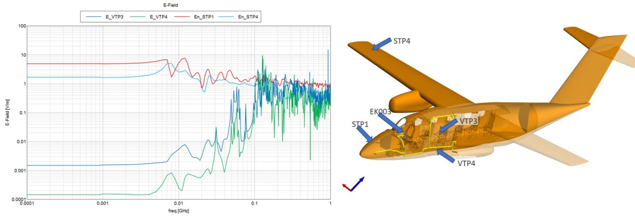
Figure 4 shows an example of an analysis carried out for a HIRF benchmark. The goal here was to simulate the induced fields at various locations on and in a small aircraft, and to calculate the induced currents at cable terminals inside the fuselage. The plane was illuminated by a plane wave excitation and the analysis was required to cover a broad frequency range from 100kHz up to 1GHz. The challenge here is that the largest electrical dimensions of the plane are approximately 50 wavelengths at the highest frequency. In order to solve the benchmark efficiently, the frequency range was divided into five frequency sub-ranges, such that different mesh densities could be assigned to each range. FEKO’s Method of Moments (MoM) solver was used for the first two frequency ranges up to 100 MHz, while the MLFMM solver was used for the remaining 3 frequency ranges. This proved to be the most efficient approach to analyze the benchmark. From the simulated responses we can see that below ~5MHz the fields are constant. As the frequency increases we can see some resonant effect occurring, as well as an increase in the amplitudes of the 2 points inside the plane as the coupling of the external fields through the windows increases.
Lightning – Lightning analysis is conceptually similar to the above benchmark, but differs in two aspects, namely the frequency range and excitation type. Typically, lightning pulses are assumed to have a maximum bandwidth of a few MHz. The lightning pulse currents are mostly introduced into the simulation model using current sources fixed at 2 points on the plane fuselage – the strike point and exit point. Figure 5 shows such a simulation setup and the associated waveforms. FEKO offers time analysis capabilities enabling different pulse variations to be compared in a postprocessing step.

The increased use of lightweight and composite materials, like carbon fiber and radar absorbing material (RAM), has further motivated the need to use simulation for aerospace applications to help understand and predict the increasingly complex field interactions and couplings that occur when these materials are used. Materials like carbon fiber can be modeled in FEKO, making it possible to analyze, for example, how the fiber orientation influences coupling into the fuselage.
SHIELDING EFFECTIVENESS:
With the ever-increasing digital processor and bus speeds in electronic systems, unintended radiation from components and PCBs is becoming a more relevant issue. Designing electronics shielding for these systems is often a tradeoff between suppressing radiation and still providing sufficient airflow for heat transportation and cooling of the electronics. Figure 6 shows the simulated shielding effectiveness for a PC tower from 100MHz-12GHz. While the behavior between 3-12GHz is relatively predictable (varying between -15 and -30dB), the behavior in the lower band is more interesting. For example, strong resonance phenomena can be seen at 334MHz and 1.78 GHz.

Upon further inspection of the field distributions in the PC tower, it can be seen that these are caused by cavity modes that is are resonant in the tower. This is clearly visible at the lower frequency and less at the high frequency due to higher order modes. This example once again illustrates the advantage of a simulation-based approach – insight into the root cause of the problem was obtained through inspection of the near-fields (which in this case would be complex to measure). Based on this insight a design modification can be made to suppress resonant modes and improve the shielding effectiveness in this frequency range.
For some shielding applications, material models with more advanced properties are required, like ferrites and frequency selective surfaces (FSS). FEKO offers extensive material modeling possibilities, including the ability to handle ferrite materials, and also offers special features to design FSS structures efficiently.
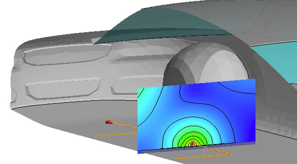
In addition to the electronics applications shown here, FEKO is also used to calculate shielding in automotive applications. Here the analysis is typically related to calculating how the vehicle chassis suppresses the magnetic fields that are radiated, for example, from battery cables in electric and hybrid-electric vehicles. In this case, the frequencies of interest are typically much lower, in the kHz range. In this range the skin depth of the steel is comparable to the thickness of the chassis. From a numerical point of view, it is important that this is modeled correctly, something that FEKO also offers a special formalization for. Figure 7 shows the simulated magnetic field radiated from a cable inside a vehicle at 10kHz.
CONCLUSIONS
While a broad range of different EMC applications from various industries were shown in this article, the main goal was to demonstrate how companies are embracing the use of simulation in the EMC process. While EMC was previously considered a verification step that was required at the end of the product development, simulation offers a platform to incorporate EMC during the product development, whereby increasing the likelihood of passing the final EMC certifications and at the same time reducing the number of physical prototypes. In the broader scheme of things this is our understanding of simulation driven design – it is a paradigm that we are seeing many of our customers are embracing going forward in their product designs.
REFERENCES
[1] U. Jakobus, R. Marchand & D, Ludick, “Aspects of and Insights Into the Rigorous Validation, Verification, and Testing Processes for a Commercial Electromagnetic Field Solver Package” IEEE Transactions on EMC, Vol. 56, No. 4, Aug 2014
[2] M. Klingler, S. Benhassine & Y. Merle, “Comparisons Between Time-Domain and Frequency-Domain Simulations Applied to an Entire Vehicle – Workshop presentation – 9th International Symposium on Electromagnetic Compatibility” EMC Europe, Wroclaw, Poland, 13-17 September 2010.


