Read other posts in the “Elephant in the Test Room” series here.
Recap On this Thread
The room: MIL-STD RF immunity testing – 1-18GHz 200v/m
The elephant: everyone in the room is aware that a significant fraction of the ‘calibrated’ 200v/m test field is actually created at the wrong test frequency.
The culprit: notoriously high ‘start of band’ harmonics produced by all octave band TWT amplifiers.
The consequence: equipments purportedly demonstrated to be resilient to 200v/m have in many instances been exposed to only around half this field strength, the rest of the test field created by an unintended frequency.
Hi again. In the last posting we had a look at filtering combined with band overlap. We have yet to determine the losses introduced by the filters, but it makes sense to postpone this exercise until we have fully explored the use of solid-state amplifiers, so solid-state is the main thrust of this post.
First, let’s finish the review of the ‘get around’ solution suggested by a blog reader. The reader suggested that to get around the TWT amplifier high harmonics issue, the test should be run backwards – that is start at the highest frequency and step downwards to the lowest frequency.
Here is the ‘hole’ in this ‘get around’. Let’s say the test operator follows this advice and the EUT fails at 1GHz but did not fail at 2GHz. The operator can conclude that the EUT is susceptible to the 1GHz field and not susceptible to the unintended 2GHz harmonic field hidden in the 1GHz test field.
Yet here is how a conversation might go between a savvy customer (represented by the EUT design engineer) and the test house (represented by the test house manager).
—————————————————————–
Design engineer: “Your preliminary test report says my design failed at 1GHz. What was the level of the applied test?”
Test house manager: “The test system applies a field strength of 200v/m at a frequency of 1GHz.”
Design engineer: “I hear you are using TWT amplifiers. These have high harmonic levels at the start of the band. How much of the 1GHz test field is in fact at 2GHz?”
Test house manager: “We have not actually measured the level of the components making up the field, but we can calculate from the amplifier harmonic power level and the antenna gain plot that the 2GHz component is about 70v/m.”
Design engineer: “So my design fails at 1GHz with a field strength of around 130 v/m?”
Test house manager: “Correct.”
Design engineer: “OK, let me revisit my design and resubmit the DUT for test. To be sure of the fix, I want the 1GHz field to be 200v/m at 1GHz, but I guess that by extrapolation, we will be stuck with 108v/m at 2GHz too.”
Test house manager: “The system can probably just about make the 200v/m at 1GHz. However we still need to see how we make an accurate calibration for this (since we can’t use the field probe), and how we justify the change in the test report required by your customer. The trouble is that for consistency, we really should do this for the first 20% of the band for all three TWT amplifiers. I guess we can say in the report that you requested extra testing. Will your customer be willing to pay for the extra testing?”
Design engineer: “Oh boy, unlikely, I guess we are stuck with the existing ‘under-test’ situation. I am not impressed with the service you are selling to me, your system has a serious problem – how much did you say you guys paid for it?”
Test house manager: “I really don’t want to be reminded of that right now.”
—————————————————————–
I am sure you would agree this situation is far from a satisfactory for either party in the conversation. So let’s continue with our efforts to dislodge the elephant.
The Solid-State Approach
Compared to TWT amplifiers solid-state amplifiers provide the following advantages/disadvantages:
- Advantages:
- Vastly superior harmonic performance
- Less prone to catastrophic failure
- Disadvantages:
- Upper frequency limitation of currently available broadband models
- Only economically viable for newly installed systems or when the 1-2.5GHz 250W TWT amplifier in the existing suite has failed or reached the end of it’s useful life.
Solid state broadband amplifiers typically display harmonic power levels 20dBc (one one-hundredth) below the power level of the intended test frequency. This means that if the intended frequency power level is 200W, the unintended power is 2W. Perfect.
Also, if a failure does occur, it will likely involve replacing one or two transistors, not the replacement of the tube. Replacing the tube in a TWT amplifier is no small affair and often costs about the same as buying a new TWT amplifier.
However for broadband power levels of 250W, the solid-state upper frequency stops around 4GHz (more recently 6GHz), so we are still going to need TWT amplifiers to get to 18GHz.
And as ever there is the issue of price. If you already have $200k or so tied up in your existing suite of TWT amplifiers you will be reluctant to invest even more. The approximate investment price for today and 3-5 years ago (what was paid for existing TWT amplifier suite) is:
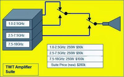
- 1-2.5GHz 250W New $90k (existing suite price was probably around $60k)
- 2.5-7.5GHz 250W New $90k (existing suite price was probably around $60k)
- 7.5-18GHz 250W New $100k (existing suite price was probably around $70k)
So we are looking at around $280k new, $190k existing (ignoring depreciation).
Reminder – A rule of thumb with TWT amplifiers is that once you are 20% into the band of operation, the harmonics have improved by around 10dB.
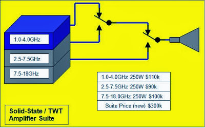
So to solve the high harmonic problem in a suite of TWT amplifiers (that is the bands of 1-2.5GHz / 2.5-7.5GHz / 7.5-18GHz) we need solid-state to cover the wanted test signal over 1-1.3GHz, 2.5-3.5GHz and 7.5-9.6GHz. The 7.5-9.6GHz won’t happen any time soon, but we can cover the first problem area with a 1-2.5GHz 250W amplifier, and the first and second problem area with a 1-4GHz 250W amplifier.
A quick search on-line shows the following solid-state models:
- 1-2.5GHz 250W $90k (solves one third of the issue)
- 1-4GHz 250W $110k (solves two thirds of the issue)
- 1-6GHz 200W $200k (still only solves two thirds of the issue, but also suitable for 1-6GHz medical testing).
- Note these are fairly recent arrivals so the price is an educated guess.
The first two are so similarly priced that for the purposes of this exercise we will go with the 1-4GHz model. Models providing this power and frequency band are available in dual-band and single-band versions. These have equal merit since this application has no need of instantaneous bandwidth (the EMC software simply switches bands at the appropriate time in the test). We will discount the third amplifier as prohibitively expensive. The two figures below show the all TWT amplifier and the proposed Solid-State / TWT amplifier arrangements with today’s prices. 
 Easy for me to say I know, but at only 7% higher in price and yet with two thirds of the harmonic issue solved, I am going with the solid-state / TWT amplifier proposal. To be continued………… Next time we will look at the filter solution for the 7.5-9.6GHz problem area. And then – spoiler alert, we will introduce what this topic was always leading to: using telecom industry linearization techniques to remove the elephant once and for all.
-Tom Mullineaux


