A.H. Systems recently sponsored an EMC Live webinar on selecting antennas for today’s test requirements in which I introduced a simplified method of establishing the amplifier power required by an above 1GHz RF immunity system. Existing methods, such as slotting numbers into a spreadsheet, do not provide the necessary visualization of the test system behavior, and provide little or no understanding of the system dependencies.
It will aid understanding if you watch the presentation before going into this thinking behind the webinar’s creation. A recording of the webinar can be found here.
The webinar supporting notes can be found by clicking the ‘Tech Notes’ tab on the A.H. Systems website www.ahsystems.com
And so, here is the thinking that led to the simplified method.
Taming the Field Strength Equation
A first glance at the beast that is ‘the field strength equation’ can create a feeling of foreboding. But studying and classifying its component parts not only tames the equation, it also gives superb visualization on how the system behaves across the band of interest. The equation is:
Where E is in v/m, d is the distance (set by the standard so a constant), G is the linear gain of the antenna, and P is the RF power injected in at the antenna connector.
Regular blog followers will know we showed how this equation was derived in a previous blog posting
www.emc-zone.com/2014/02/the-linearization-of-emc-amplifiers.html
We start the taming process by recognizing and pulling out the obvious and hidden constants within the equation. We then take a brand new step where the field strength E itself is made a constant. In order to do this we introduce a new compensatory factor called ‘Beamwidth Loss’. More on this later.
Obvious and Hidden Constants
The obvious constant is √30 / d. We will call this constant k1
The less obvious constant is √(PG). Note, we are not saying that P or G is a constant, we are saying for a particular fixed field strength E, that P multiplied by G is a constant.
Let’s say P = 10 and G = 10. Therefore P.G = 100 which means √(PG) = 10
If at another part of the band the antenna linear gain G was to drop from 10 to 5, then for P.G to maintain its constant value, the power P would need to compensate by increasing to 20, keeping P.G = 100 constant and √(PG) = 10 constant.
And so P and G do a sort of dance across the band, where as G changes, P changes in the opposite sense to maintain the constant. We could allocate this constant a letter, but for our purposes we will keep it as √(PG), we just need to keep in the back of our minds that this has a constant value for a fixed field strength. So we will stick with
This says that for a fixed field strength (let’s say the minimum allowed field strength stipulated in a standard such as 61000-4-3), any change in G is compensated for by a change in P. All makes sense and stands to reason.
Now we have a better feel for the equation dynamics (the dance), we turn our attention to its real use in the webinar, which is to determine the power required to obtain a particular field strength.
First we rearrange to make P the subject of the equation.
For fixed field value Ek
Taking 10 log10 of both sides puts the equation in dB notation
With logarithms, a linear division is represented by a subtraction, so we can write
What this says is that the power required from the amplifier (assuming it is connected directly to the antenna, that is with no cable loss) is a power level dictated by constants, minus the antenna gain in dBi. In other words, the better the gain of the antenna, the less power required from the amplifier.
Again, this all makes sense and stands to reason.
Note that for the case where the linear antenna gain is 1 (equates to G = 0dBi), the amplifier power level is entirely dictated by the constants. For this reason we will call this power level the ‘base power level’, and we will regard GdBi as a modifier to this level.
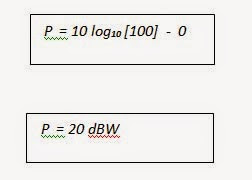
So what is the amplifier’s base power level for a 61000-4-3 RF immunity system where the test distance d is 3m, and the minimum permitted field level (our Ek) at distance d is 18v/m?
We will round [32(18)2 / 30] = 97.2 up to 100W
Amplifier power is more commonly stated in dBm, that is the power is relative to 1 milliwat, not 1 watt. The conversion from dBW to dBm is simplicity itself – just add the number 30.
So our base power level is 50 dBm or 100W. We now have a starting point for our system.
Why did we go the dB route? Answer – because antenna manufacturers supply gain data in dBi, cable loss per meter is given in dB, and the soon to be introduced ‘beamwidth loss’ is in dB. The beauty of everything being in dBs is we can just add these algebraically to get the overall system Gain and then simply add this algebraically to the base power level to get the power required from the amplifier.
Don’t forget that the webinar and the supporting notes offer further explanation, particularly regarding visualization of the system wide performance.
Next time we will introduce ‘beamwidth loss’, rationalize its introduction, use it to determine the overall system gain GSYS, and finally use the worst-case GSYS and the base power level to determine the power required from the amplifier.
To be continued ………
-Tom Mullineaux
Lionheart Southwest


