The Simplified Method of Establishing the RF Power Required by a RF Immunity System Continued…
Previously we presented the novel idea that the RF power required by a RF immunity system is a base RF power level (determined entirely by constants), minus the gain of the antenna. The basic principle is shown pictorially in Figure 1. The picture says the system RF power requirement in dBm equals the base RF power level in dBm, minus the antenna gain in dBi. A quick sanity check says this makes sense in that the higher the antenna gain, the less power required by the system.
 |
| Figure 1 |
The approach is also self-correcting in that should the linear gain of the antenna drop to less than 1 as can happen in lower frequency test systems (say SANT / SISO = 0.9), the gain in dBi will become minus, resulting in the system power requirement equaling the base power level PLUS the antenna gain.
So far so good.
We then built on this by converting all phenomena requiring more system RF power into loss-blocks and adding the loss blocks to the system diagram as shown in Figure 2.
 |
| Figure 2 |
Later on, we will simply add the overall dB loss of the blocks to the antenna dB gain to obtain the ‘overall system gain’ such that we are back to Figure 1, with the rightmost block amended to represent the system gain.
This approach, combined with the graphical representation described in the AH Systems webinar [Link Here] provides superb understanding / visualization of the system behavior across the band of interest, and uses the power of dB notation to simplify power computation.
In this particular blog entry we will concentrate on the mismatch presented to the system by the antenna.
Generating the VSWR Loss-Block
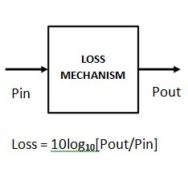
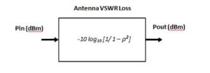
We need to convert the antenna VSWR phenomenon into the ‘basic loss-block form’ shown in Figure 3.
 |
| Figure 3 |
Please Note: this section also gives the solution to the teaser question posted last time.
The VSWR loss-block must obey the form of the equation in Figure 3, that is:
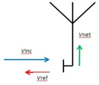
We need to establish Pout / Pin. We start with the classic VSWR representation as applied to an antenna shown in Figure 4a. Note in all cases below, the antenna symbol represents any type of antenna and the measurement plane is at the antenna connector.
 |
| Figure 4a |
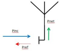
The figure shows the incident voltage Vinc striking the measurement plane, a portion of Vinc passing through the measurement plane to the antenna (shown as Vnet, the net voltage used by the antenna to create the test field), and a portion of Vinc being reflected back along the transmission line (the reflected voltage Vref).
By inspection we can see that Vinc is the input to our loss block and Vnet is the output. Again by inspection
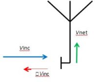
Here we introduce ρ, the reflection coefficient at the measurement plane. This is equal to the ratio Vref / Vinc, so Vref can be written as ρVinc. This is shown in Figure 4b.
 |
| Figure 4b |
 |
| Figure 5 |
We still want Pout / Pin so we need to convert Figure 4a to the power based diagram of Figure 5
So the
of Figure 4a becomes the
of Figure 5
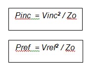
To do this we convert all voltages to power with reference to the characteristic impedance of the transmission line (cable). That is: –
For future reference that is
And
So the
Of Figure 5 becomes
Pnet (that is Vnet2 / Zo ) is the output of our VSWR loss-block in Figure 2 and Pinc (Vinc2 / Zo) is the input
Rearranging to make Vnet2 / Zo the subject of the equation
But looking again at Figure 4b, Vref = ρVinc, where ρ is the reflection coefficient presented at the measurement plane
That is
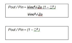
Dividing throughout by Vinc2 / Zo will give us our Pout / Pin (since Pin is Vinc2 / Zo)
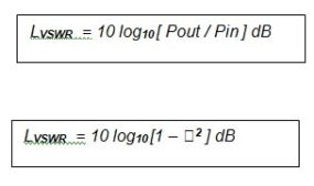
The final step in the conversion to a loss-block is to take 10log10 of this
One last little trick and we are there.
So
And at last we have our VSWR loss-block (Figure 6)
 |
| Figure 6 |
As a sanity check we should test this to see if the block works for ρ = 1 (100% reflection at plane) and ρ = 0 (No reflection at all)
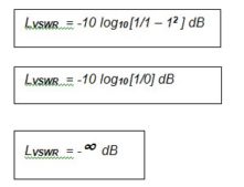
When ρ = 1, none of Vin gets through the measurement plane and the loss should be infinite
When ρ = 0, all of Vin gets through and the loss should be 0
So testing for ρ = 1
Correct
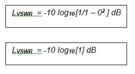
And testing for ρ = 0
But log10[1] = 0, so
Correct
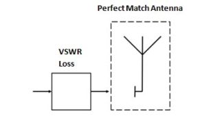
As a further step, we can now place this VSWR Loss-Block in front of a perfect match antenna (VSWR = 1:1 over the entire antenna frequency range).
 |
| Figure 7 |
To be continued…
-Tom Mullineaux
Lionheart Southwest


