Donald L. Sweeney and Marilyn Sweeney
D.L.S. Electronic Systems, Inc.

Mitigating Excessive Emissions was originally written in 1988 and presented at the IEEE EMC Symposium in Atlanta Georgia. The concept and paper have been used by the author hundreds, if not thousands, of times to illustrate what he calls “The Barbell Model.” This illustrates, in very simple terms, how radiation can be properly confined by terminating shielded cables properly, filtering wires, adding filter capacitors and even decoupling integrated circuits. The original paper is being updated to give additional background about how the concept was used to evaluate a mountain against EMP and how the concept applies to susceptibility, as well as to update many of the drawings.
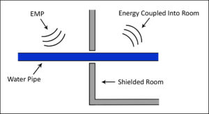
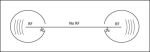
I understand many years ago when Cheyenne Mountain was evaluated for nuclear hardness to EMP (the electromagnetic pulse when a nuclear weapon is detonated), a similar concept was used. When you realize the difficulty of doing real life testing of a nuclear blast on a mountain you can appreciate the advantages of using a simpler technique. I understand that in the process of the evaluation, an EMP weakness was found where a water pipe entered a shield room without being terminated. As you read through this paper, you will learn that this is the worst case termination possible, none at all! (See Figures on right.)
Often, when communication is required between electronic devices, unwanted RF energy is combined with it. This unwanted RF energy can be controlled or reduced by proper consideration being given to the topology of the system. The following explains many of the ways in which this unwanted RF energy can be controlled or mitigated and describes some of the ways in which the control may be compromised.
The number one problem in electromagnetic compatibility (EMC) has always been radiation from external cables. The materials needed to solve this problem are generally present, but are not being used properly.

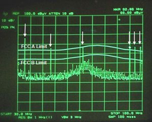
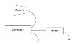
Figures 1A and 1B show a typical computer system as it often arrives at a test facility. The interconnecting cables and even some of the peripherals are emitting RF energy. Throughout this discussion, an analogy is used where the electronic product is represented as a conductive sphere (the ball of what will become our barbell) connected by the handle or shield of the cable as shown in Figure 3.
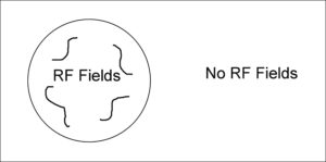
Obviously if electromagnetic fields were kept inside of a conductive sphere, there would be no unwanted RF energy on the outside. (See Figure 2) This containment, however, is impractical since wires, such as ac power, keyboard communication and data via parallel and serial interfaces must pass in and out of the sphere. Thus, the spheres need a way to communicate while inhibiting unwanted emission.
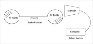
One way to accomplish this protected path is to build one circuit in a sphere and communicate via a hollow bar to another sphere, thus expanding the analogy to a barbell. The spheres in Figure 3 represent a personal computer (PC), and the hollow bar represents an interconnecting shield to a monitor with the two circuits communicating with no external fields. The spheres and interconnecting passage allow communications inside the barbell. This concept can be used at any level of complexity.
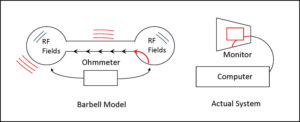
The barbell is a difficult way of actually connecting two circuits, but this concept will be used to develop a more practical approach. Figure 4 is the barbell model showing the way shielded cables are often improperly connected to equipment.
The bar, which is the shield on the cable, is connected to one of the spheres with an internal pigtail. A pigtail is a short length of wire used to terminate a shield. The resistance of the internal pigtail may not greatly exceed that of the connection of an ideal barbell model, but the internal pigtail acts as a receiving antenna and couples the RF energy outside of the sphere, via the bar. The bar and the second sphere now radiate the RF energy which was originally inside the first sphere.
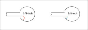
An example of improper use occurred when a manufacturer used an 8-inch wire as a pigtail, which caused his equipment to be out of limit. Shortening the pigtail to 1 inch brought the system into compliance. Another example of improper use was a pigtail 3/4-inch long tying the shield of an RS232 connector to a metal chassis (Figure 5). The unit was at the limit of RF emissions until the wire was shortened to 3/8 inch. Measured emission dropped by 6 dB which can be calculated using: 20 Log (L1 /L2) or 20 Log (0.75/0.375) = 20 Log 2 = 6 dB.
I have seen testing to 200 V/m with a cable terminated with a 20 inch pigtail. In this case, we are not radiating energy, but just the opposite. The energy from the transmitting antenna is being picked up by the pigtail as if it were a receiving antenna causing the energy to enter inside the device. With 200V/m it is very unlikely a system could ever pass radiated susceptibility under these conditions. (See the section SUSCEPTIBILITY LESSON LEARNED near the end of this article.)
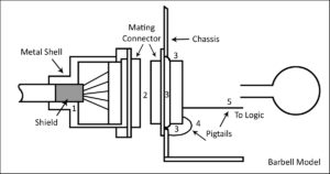
The ideal way to terminate is to connect the bar to the ball of the barbell using a 360-degree connection as shown in Figure 6. In this figure, the shield makes 360-degree contact to the metal shell at point 1. The metal shell makes a 360-degree contact to the mating connector at point 2, as does the mating connector to the chassis at point 3. This arrangement can be seen using the barbell model as a continuous connection. The barbell model can be compromised with pigtails and logic grounds as shown at points 4 and 5. The potential for emissions at points 1 through 5 are now considered in detail.
IMPROPER CABLE TERMINATIONS IN COMMON USE
The ideal termination in Figure 6 is often compromised in one of five ways.
1. Failure to Tie the Metal Shell to the Shield (See Point 1, Figure 6).

To be properly terminated, the metal shell of the connector must contact the shield. In Figure 7A, the shell is insulated from the shield by the vinyl jacket of the cable. The vinyl creates a small gap. Emission resulting from gaps is examined in 2. below. In Figure 7B, the vinyl has been partially removed to enable direct contact between the shell and the shield, thus providing a continuous confinement of RF field.

2. Use of Plastic Mating Connectors (See Point 2, Figure 6 and Figure 8).
Plastic should not be used on the body of the mating connector because it prevents electrical connection between the metal shell and the metal chassis, thus creating a small gap. Both mating connectors should have metal or at least conductive shells.


One might conclude that the small gaps at Points 1 and 2 of Figure 6 would not cause a problem because so little energy can seemingly exit from a small gap. However, RF energy is induced on the wire inside the sphere (Figure 9). This energy then passes through the shielded cable on its wires and is coupled to the shield by stray capacitance. Since the energy has no path to return to the sphere because of the gap at A, the energy flows out onto the shield and radiates.
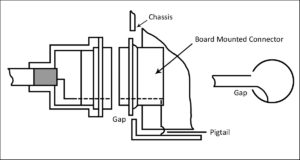
3. Use of Non-Bulkhead, Board-Mounted Connectors (See Point 3, Figure 6 and Figures 10a & b).
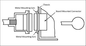
A major compromise in many designs is the use of board-mounted connectors without contact to a chassis. This condition, as shown in Figure 10A, is in effect, a pigtail from the shield to the chassis. In a correct installation, the connector would have metal mounting ears, which are terminated to the chassis as shown in Figure 10B.
4. Incorrect Use of Drain Wire (See Point 4, Figure 6 and Figure 11).

As shown in Figure 11, a drain wire is sometimes used improperly to terminate the shield to the chassis when the shield does not connect to the metal shell of the connector. This arrangement should be avoided, especially at higher frequencies, since the drain wire forms a pigtail similar to that in Figure 4. This pigtail picks up and couples energy through the pin of the connector out onto the shield from which it radiates.
5. Use of Drain Wire to Logic Ground (See Point 5, Figure 6 and Figure 12).

In Figure 12, the drain wire from the shield is connected directly to logic ground. This is improper in that it forms a pigtail, which may not reach the chassis except through the power supply. In an installation like this, the logic ground circuit is continuously injecting RF current into the pigtail. This indirect route makes the pigtail the longest of all the examples and possibly the worst case discussed.

FILTERING AS A WAY OF CONFINEMENT

The following are three ways in which the continuous metal shield can be removed from portions of the barbell model without increasing emissions.
1. Filtering with Shielded Cable to a Non-shielded Peripheral.
A system such as a PC, which is completely shielded, can be connected to a poorly shielded device such as a printer and still pass emission requirements. This is explained by the capacitance between the shield and the internal conductors as seen in Figure 13. While the energy is passing through the wires in the shielded cable, it is being continuously removed and returned to the PC through the shield. This capacitance often acts as an adequate filter to remove RF, enabling a non-shielded peripheral to meet emission requirements. It will only work if the connection at the source end (PC) is well terminated.
2. Filtering with a Capacitor.
The next step in examining the barbell analogy is to remove the bar from the model completely, thus eliminating the shielding on the cable. The bar can be removed if all RF is eliminated from the wires before they leave the sphere. RF can be removed by a filter where the signals exit the sphere.
Figure 14 represents a non-shielded cable with RF riding on it. The confinement of the RF field has been compromised to a point where there is no shielding over the wires. The RF needs to be confined in the spheres. This confinement of the RF should not prevent the communication. The goal of confining RF and allowing communications can be accomplished by providing an RF short circuit at the point where the wire exits the sphere as shown in Figure 15.
This shorting of the wire differs from a pigtail in that a pigtail is an extension of the shield and is not RF shorted as it enters or exits the sphere.
The RF shorting of the wire is accomplished by using aproperly selected capacitor as a filter at the point of exit. This capacitor must allow the intended communications to pass and short RF to the sphere. The capacitor can take several forms, such as a discrete capacitor, a connector with a capacitor built into each connection, or a feed-through capacitor. The highest quality of these three would be the feed-through capacitor. The choice of capacitor is determined by the frequency to be filtered, the number of connections, and the cost. Filtering with capacitors as described can be used for signal wire and for power cords. It must be noted that the capacitor is much like a pigtail in that its wire lengths are critical. Since there is inductance in the leads of the capacitor, the ideal length of the leads would be 0, or as close as possible to 0. If a single capacitor does not work, a combination of capacitors and inductors can be added to build an L, T, or Pi filter that should solve the problem.
3. Filtering by Decoupling.
The barbell analogy can be applied to an integrated circuit, which needs its energy confined with a decoupling capacitor as seen in Figure 16A. Figure 16B shows the large loop area of poorly confined RF energy when the decoupling capacitor is placed at a great distance from the integrated circuit. In Figure 16C, the area of confinement is greatly reduced by moving the decoupling capacitor near the integrated circuit.

SUSCEPTIBILITY LESSONS LEARNED

The original “Mitigating Excessive Emissions” paper was an explanation of how emissions are generated by a current flowing in a loop and how the levels of emissions are very dependent on the area of the loop as well as the current level.
Since then, the concept has been explained to probably thousands of people over the years.One of the worst situations I can remember was a product that was required to meet 200V/m. When the product failed, we examined it and found there were a number of communication links with 20 inch pigtails. The question has always been in my mind, “How much voltage is being induced with a 20 inch pigtail?”
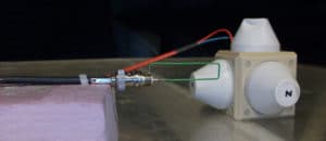
Since the author has always wanted to apply the barbell concept to susceptibility using scientific experimentation, he generated two tests with the same area but different wire lengths, and presents data from three experiments to show real numbers of the voltage picked up when doing susceptibility testing.

1. Measuring the Induce Voltage Using a 20-Inch Pigtail as a Square Loop 5 cm by 1 cm
The assumptions:
- The pigtail is 20 inches or 50 cm
- The return is 1mm away (the thickness of the insulation)
- The loop area is .1 cm by 50 cm = 5 cm2
- We will use a loop of 5cm by 1 cm
- Load used would be the input impedance of the instruments
- (50 Ohms)

This experiment was done twice, once with an area of 5 cm2 as described above and again with an area of 2.5 cm2 which is ½ of both the area and the length of the previous experiment. See Figures 17 and 18 and the data in Tables 1 and 2 that show a 6 dB difference at 200 MHz.
When applying the concept to susceptibility, it turns out to be more of an E-Field pickup than a current loop emissions problem. You will see that with the same 5 cm2 loop area we get far different results using the two approaches.
2. Using a 20-Inch Pigtail as a Wire 50cm Long and Its Return 1 mm Away.
We have the same area but a far different wire length. The original thinking of using a pigtail was to demonstrate emissions, which are caused by current flowing in a loop and is thus area dependent. Since we were trying to demonstrate pickup from an E-Field, it became apparent the length of the pickup antenna (pigtail) would be important not just the area. We tested a loop made from a 20-inch wire with the same effective loop area.
The assumptions:
- The pigtail is 20 inches or 50 cm
- The return is 1mm away (the thickness of the insulation)
- The loop area is .1 cm by 50 cm = 5 cm2
- We will use a loop of 50 cm by 1 mm
- Load used would be the input impedance of the instruments
- (50 Ohms)
Using the same 5 cm2 loop area as in Table 1 but a much different pigtail length of 20 inches (see Figure 19) we get a much higher induced voltage as shown in Table 1 and 3 at 200 MHz Z-Axis.
SUMMARY
Today a major EMC compliance problem is radiation from cables. A model has been developed which allows an understanding of how RF energy needs to be confined. This confinement is sometimes compromised by an open circuit, a gap, or a pigtail. The barbell model shows how the energy can be confined by properly terminating shielded cables, filtering wires, adding filter capacitors, and decoupling the power and ground of integrated circuits. If you use this process to analyze your system and make the necessary adjustments, you will have fewer problems involving RF radiation see figures 20A and 20B.
Experimental data was generated where both the wire length and area was changed by ½ and the energy picked up changed by 6 dB (compare Table 1 and Table 2 at 200 MHz).
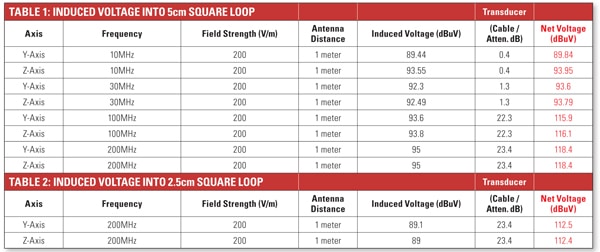 Experimental data was also shown using the same loop area but dramatically different wire lengths. From this data one can conclude with long pigtails (20 inches) one could not expect to pass 200 V/m susceptibility testing as shown in Table 3 at 200 MHz.
 Remember that the ideal length of a pig tail is “zero.”
ACKNOWLEDGEMENT
The author’s concept of the barbell was developed from personal conversations with Dr. Werner Graf who had previously presented a paper by E. F. Vance and F. M. Tesche entitled “Shielding Topology in Lightning Transient Control,” NASA Conference Publication 2128 FAA-RD-80-30. Thank you to Tim Lusha of D.L.S. Electronic Systems, Inc. for running the experiment using the 5 and 2.5 cm loops.
