Clean transmission of signals from the EUT.
Jorg Hacker
Langer EMV-Technik GmbH
It is uncommon to use an oscilloscope to monitor signals from the EUT when testing immunity to interference. The complicated environmental conditions in the anechoic chamber during RF irradiation or burst and ESD tests lead to measuring errors and unwanted interference in the EUT. Modifications to the EUT are accordingly done by “trial and error.”
These difficulties can be overcome by careful measurement using small and interference-immune measuring systems. Causes for malfunction are quicker to find this way.
1 AIM OF THE MEASUREMENTS
1.1 Detect Interference
Interference is traditionally detected by observing the EUT. The subjective nature of this observation introduces inaccuracies. Automatic testing procedures are not possible. Electronic display monitoring or measurement of output signals from the EUT can help in this situation.
1.2 Trace Back Disturbed Signals
EMC practice is often complex. Interferences in EUT can occur simultaneously at different places via different modes of action. To eliminate errors effectively, it is crucial to analyse disturbed signals from the EUT. This concerns the disturbance of signals in both digital and analogue systems.
These measurements allow conclusions to be drawn as to the cause of error as well as an evaluation of the effectiveness of EMC measures directly at the site of interference.
2 REQUIREMENTS FOR MEASURING EQUIPMENT
2.1 General Requirements
Injecting disturbances, e.g. using a line impedance stabilization network on the burst test station, produces physical quantities in the EUT such as current, voltage, magnetic field and electric field. Their spatial distribution, intensity and orientation are determined by the geometric structure of the metallic system of the EUT and measuring station. They are almost impossible to predict given the complexity of the EUT.
These quantities also act on the measuring equipment, such as the probe tip and measuring lines, but must not be allowed to cause false readings. What field strengths must the measuring equipment be able to withstand?
In the case of ESD, the entire disturbance voltage can exist between the metallic housing and the PCB insulated against it. At a distance of 5 mm, 5 kV ESD creates a field strength of 1 kV/mm, i.e. 1 MV/m! The disturbance current flowing through the EUT produces magnetic fields in the range of several milliteslas.
The field strengths are much lower for RF irradiation, and reach up to about 200 V/m, depending on the test requirements.
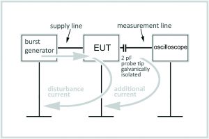
To achieve error-free measurements under these conditions, the EUT and measuring equipment must be galvanically isolated. Only then will the path of the disturbance current in the EUT not be impermissibly modified. It must be noted here that an optocoupler, for example, used for galvanic isolation possess a parasitic capacity of a few pF between the primary and secondary side. It depends on the EUT construction as to how much this capacity will transmit impermissible disturbance current (Figure 1). Optimally, the measurement should be done using fibre optics, since then hardly any parasitic capacity exists at all. It also rules out any change in the disturbance fields by additional cables. It does, however, require a probe tip that converts the signal to be measured into a light signal and which is itself so small that it does not impermissibly deform the disturbance fields.
2.2 Measuring Analog Signals
2.2.1 Mechanism of Interference
Especially critical for analogue systems are RF irradiation via the antenna and RF coupling in the lines. Most analogue systems are resistant to burst/ESD errors, since there band with is not high enough to detect these short disturbance pulses.
High-frequency electric and magnetic fields are coupled into the EUT from the electromagnetic field through the EUT surface or via connected leads. These fields produce disturbance voltages on signal lines and in the GND system. Modulation of the RF disturbance field is especially problematic. The standard demands the carrier frequency be modulated to 80% AM at 1 kHz. The RF can be demodulated at pn junctions, e.g. in operational amplifiers. As a consequence, a voltage with a frequency of 1 kHz arises, which superimposes itself over the useful signal and is carried over into the analogue signal path.
2.2.2. Requirements for the Measuring System Bandwidth

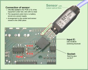
For troubleshooting, it is usually sufficient to measure the demodulated 1 kHz signal in the EUT. The RF carrier itself need not be measured. This means a small and low-cost measuring system can be used. With the help of a small probe tip with an A/D-converter, the 1 kHz error signal is converted into digital light signals and transmitted from the EUT over fibre optic cable without feedback (Figure 2).
The measuring signal in the EUT is generally superimposed with RF voltages. Upon measurement, these voltages are applied to the probe tip, i.e. the probe tip must be immune to interference at field strengths of up to 200 V/m.
Measurement Range
Practically required measurement ranges are between 5 mV (audio equipment and sensors) and 50 V (automation equipment, ASI bus, vehicle on-board wiring system). A high dynamic range is preferable. Limits are set by the small size, the transmission capacity of serial transmission and the power draw of the probe tip.
2.3 Measuring Digital Signals
2.3.1 Mechanism of Interference
Short disturbance pulses such as burst and ESD are especially critical for digital circuits. Every IC input evaluates the disturbance voltage pulse at its input with its dynamic input switching threshold. When its switching threshold is exceeded, this pulse is converted to a logical signal and fed into the program sequence. This then triggers very specific functional errors, depending on the EUT.
The interference immunity of the EUT is essentially determined by the sensitivity of the IC. The definition of a sensitivity parameter is a crucial for coping with the interference processes. It depends on the IC technology (HC, AC, VHC, etc.), on the shrink and therefore on the IC manufacturer. The scatter range of IC sensitivity for all modern IC families lies at a factor of 10. The resulting deviation of burst immunity can lie within the kV range.
2.3.2 Requirements for the Measuring System
It is difficult to produce a probe tip at reasonable cost that, on the one hand, is small enough not to interfere with the EUT and, on the other hand, transmits the rapid disturbance voltage pulses over fibre optic cable error-free at the given field strengths. It is, however, possible to introduce a special probe tip (which we will refer to from here on as a sensor) into the EUT. This sensor possesses a digital IC of known sensitivity. When this IC recognizes, with its dynamic input threshold, a voltage pulse (or disturbance voltage pulse), it emits a defined light pulse. In this way, it reproduces the interference threshold of the electronic device. A light pulse thus signifies: “A disturbance pulse has occurred in the EUT on the tested circuit that is large enough to disturb the device’s function.”
2.4 Potential Measurement
By transmitting signals over fibre optic cable, these systems are also in principle suitable for potential measurement. The only thing to ensure is the power supply of the probe tip is made potential-free, e.g. using a battery module.
This is useful for measuring, for example, transients in the intermediate circuit voltage of pulse inverters.
MEASURING STRATEGIES
3.1 Measuring Disturbances
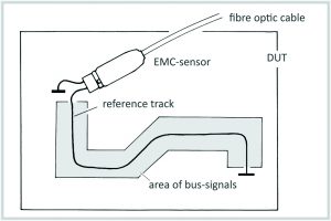
A reference interference threshold is created using a sensor and a conductive trace on the Device Under Test (Figure 3).
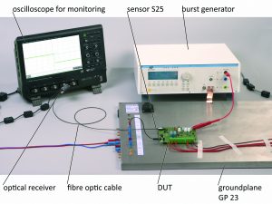
With the conductive trace, the sensor taps voltage differences over the GND system of the EUT that are caused by disturbance current in the GND system (Figure 3). When the sensor’s interference threshold is exceeded, it emits a light signal over a fiber optic cable. This is a quick way to evaluate the effectiveness of countermeasures.
This method is mainly employed for dimensioning connector systems, shields, filters and current leakage paths. It can also be employed during the developmental phase, when the EUT itself is not yet functional but information is already needed on the design of housing and filters.
3.2 Measuring Static Signals
When troubleshooting, it is useful to monitor certain signals in order to learn the instantaneous state of the EUT. Of interest are signals such as INT, RESET or PFI, which are also transmitted by a sensor from the EUT over a fibre optic cable. A counter (event counter) can summate the light pulses and thereby serve as a memory. That means continuous, concentrated monitoring of a display is no longer necessary – modifications can be made freely while the measurement is still running.
The origin of the interference can often be learnt by monitoring the signals on an oscilloscope (via fibre optics): In Figure 5, a short disturbance pulse on the RESET line of a processor signifies direct interference on this line, while a pulse in the millisecond range is caused by interference on the RESET component.

3.3 Measuring Periodic Signals
3.3.1 Monitoring the EUT
Often, it cannot be determined whether the EUT is still running during interference immunity tests. For example, the controller may have long since crashed while the LCD display still shows the correct data. The transmission of characteristic signals from the EUT is helpful in such cases. A signal such as Chip Select, for example, shows that the processor is still working.
3.3.2 Signal Monitoring
If the disturbances are coupled into the bus system, for example, then it is possible to detect disturbance pulses on the oscilloscope. Measurements are done with sensors via fibre optics, with triggering over the pulse width of the measured signal. The pulse width of the useful signal is typically larger than that of the disturbance pulses. If the oscilloscope does not have such a triggering option, or if the data and interference signal are almost equally long, then one can trigger the disturbances manually using a burst detector.
3.4 Analyzing Operating Behavior
Frequently, the data on bus systems give an indication of the operating state of the EUT. Precisely analysing the data on an oscilloscope or logic analyser is laborious in such cases. One quick option is to monitor the data stream with a counter. Naturally, given the changing data content and lack of synchronization between counter and data packets, one does not always obtain a constant numeric value on the counter. Mostly, however, specific operating states are assigned specific numeric values. The developer can therefore recognize, for example, specific pulse sequences during system start-up after RESET and infer the current operating state of the EUT. When testing immunity using this simple analytical system, it can be discerned whether, for example, the system is restarting due to interference, or whether data are being retransmitted at unusual frequency, etc.
3.5 Analog Signals
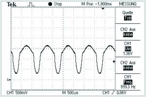
Especially in systems that use analogue data acquisition and digital processing, it is important to verify whether the disturbance lies in the analogue quantity or in the digital processing.
Figure 6 shows the output voltage of an operational amplifier that has RF coupled into its input, which demodulates and amplifies the 1 kHz signal. This demodulation can occur at practically every pn junction. The degree of disturbance is affected by the extent to which the EUT itself amplifies the demodulated disturbance voltage.
SUMMARY
Using fiber optic technology and small, interference-immune sensors, it is possible to measure signals in the EUT without feedback or error during interference immunity testing. In the case of digital systems, a simple counter is often sufficient for evaluating the behaviour of the EUT and detecting interference.


