NOTE: This article has been translated from Dutch to English. It can be found in its original language in the 2014 Europe EMC Guide.
Konika Banerjee, Marcel van Doorn and Pierre Beeckman, Philips Innovation Services, Quality & Reliability Engineering – EMC Center, High Tech Campus 26, 5656 AE Eindhoven, The Netherlands
ABSTRACT
Multimedia products need to comply with requirements to limit exposure to electromagnetic fields (EMF). Compliance can be demonstrated by using the low-power criterion by proving that the total radiated power is lower than 20 mW. This paper describes the measurement method developed to measure the maximum total radiated power using a reverberation chamber. A description of the calibration of the chamber as well as the verification of the measurement method is given. Finally, some results of measurements of actual multimedia products are given.
INTRODUCTION
Multimedia (MM) products have to comply with requirements to limit the human exposure to electromagnetic fields (EMF). Since no product-specific EMF standard exists for MM products, the generic EMF standard IEC 62311 [1] may be applied for compliance demonstration. Because of the generic nature of [1] it does not provide specific assessment methods, i.e. no technical details on possible EMF compliance test methods are described in this standard. This has given rise to the development of a product-specific standard for MM products, which is published as an ECMA technical report [2]. This technical report provides detailed guidance for the assessment of EMF exposure to the general public from MM products in accordance with [1].
The limits on EMF exposure, known as “basic restrictions,” are stated in the ICNIRP 1998-guidelines [3] and are based on established health effects. The basic restrictions are specified using different quantities in different frequency ranges. These are based on the various adverse health effects that can be caused by EMF exposure in that specific frequency range.
The quantities in which the basic restrictions are specified are often impractical to measure which makes the proving of compliance complicated. In order to simplify the compliance measurements, alternative limits called ‘reference levels’ have been derived. Reference levels correspond to the basic restrictions under worst case exposure conditions and are defined in more easily measurable quantities such as electric field strength (E), magnetic field strength (H), magnetic flux density (B), power density (S), etc.

Besides using the basic restrictions and the reference levels to prove compliance, it may be also possible to derive compliance criteria based on realistic assumptions such that a simple measurement can be used to prove compliance. This approach is considered in [1] where it is said that if the equipment under test (EUT) can be demonstrated as compliant for both intentional and unintentional emissions with the generic low-power standard IEC 62479 (i.e. average total radiated power ≤ 20 mW) [4], then the EMF requirements in [1] are considered to be met as well. This low-power limit of 20 mW is a very conservative limit that is based on the SAR-limit of 2 W/kg that applies for any 10 gram voxel (Volumetric Picture Element) of brain tissue. An overview of the types of EMF exposure limits can be found in Figure 1.
This paper describes the measurement method developed to measure the maximum total radiated power using the reverberation chamber (RvC). A description of the calibration of the chamber as well as the verification of the measurement method is given. Finally some results of measurements of actual multimedia products are given.
THE REVERBERATION CHAMBER AS A TOOL TO MEASURE TOTAL RADIATED POWER
The reverberation chamber is a well-known tool for rapid measurement of total radiated power of intentional transmitters [5]. The RvC has therefore been put forward by the authors in the editing of the ECMA TR/97 [2] as a test facility to be used in the TRP measurement method. Basically, the TRP of an EUT is determined by placing an EUT in a RvC and measuring the output power of the RvC using an rms power sensor (see Figure 2). Measuring the TRP using an RvC for EMF assessments is very convenient for the following reasons:
- the measurement method is non-invasive;
- the TRP is measured in terms of rms-power which is exactly the same metric as required for the low-power threshold level of 20 mW;
- the TRP from multiple transmitters and/or broadband transmitters can be measured in one go; and
- the usable frequency range of an RvC covers the frequency ranges that are applied generally for radio and communication transmitters.
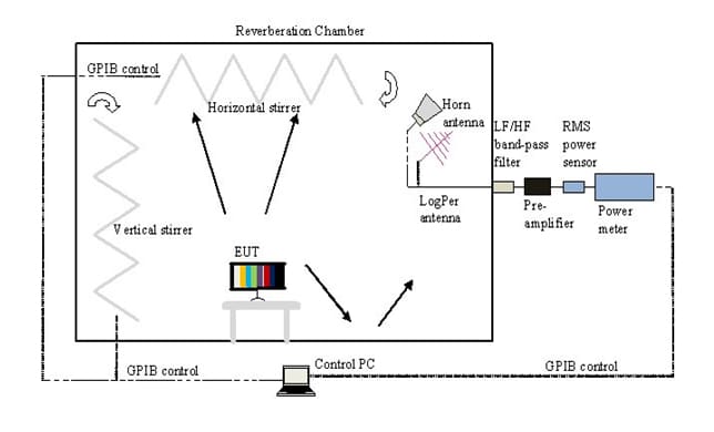
It should be noted that the method of testing described in this paper determines EMF compliance of an EUT in a specific frequency range only, namely 80 MHz – 6 GHz since this is the practical usable frequency range of the used RvC and its associated measuring equipment. In practice the upper frequency range for TRP measurements in an RvC may be much higher and depends on the frequency restrictions of the required measuring equipment. The TRP is measured over a time period of 6 minutes, this being the averaging time in the case of time varying signals for Specific Absorption Rate (SAR) values (10 MHz – 10 GHz).
REVERBERATION CHAMBER CALIBRATION
Before TRP measurements can be carried out on actual EUTs, an RvC calibration has to be performed to determine the losses which are inherently associated with the chamber. In IEC 61000-4-21 [6] detailed descriptions are given on the RvC calibration and testing methods for both emission and immunity. The calibration method described in the standard is extensive in which several factors are determined:
- ACF (Antenna Calibration Factor) – Represents the loss of the chamber based on the measured average power
- IL (Insertion Loss) – Represents the loss of the chamber based on the measured maximum power
- Field uniformity factors in x-, y- and z-direction – Represent the quality of the field uniformity of the chamber within its working volume
All these factors are determined over nine locations inside the chamber that represent the boundaries of the working volume. The stirrers of the RvC are operated in stepped mode.
For TRP measurements, it has been decided to perform a small section of the complete calibration process necessary for correct TRP measurements:
- Only the ACF is determined since the measured average power is required for the 20 mW rule.
- The ACF is determined at only one location, i.e. at the center of the working volume, this being similar to the actual application set-up.
- Power measurements are carried out in the frequency range 80 MHz – 6 GHz, this being the workable frequency range of the RvC in combination with the associated equipment.
- Continuous power measurements are carried out over 6 minutes per frequency point; 6 minutes being the averaging time for SAR in the frequency range 10 MHz – 10 GHz (see [2]).
The aim of the calibration is to determine the transfer of energy between the transmit antenna and the receive antenna. This gives an indication of the inherent losses associated with the RvC.
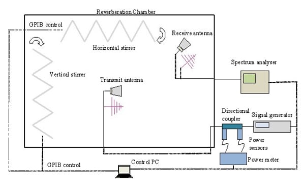
In Figure 3, a block diagram of the RvC calibration test set-up is depicted. The RvC has two stirrers (horizontal and vertical) which are set to a continuous stirred mode, both having different speeds such that modes in the chamber are not repeated. Two types of antennas were used depending upon their effectiveness in certain frequency ranges, namely, a log-periodic antenna for frequency range 80 – 1000 MHz and a horn antenna for the range 1 – 6 GHz. The transmit antenna is placed in the middle of the working volume of the chamber at a height of 1 m above the floor. This position of the transmit antenna is chosen such that it emulates the position of an EUT during actual TRP measurements. A known level of power is injected into the RvC with the use of the signal generator and transmit antenna. The directional coupler and the power meter are used to determine the forward and reflected powers so that losses due to mismatch are accounted for. Per frequency point the average power is measured by the receive antenna and spectrum analyser over a period of six minutes.


For correct TRP measurements it is necessary to determine the average power so that this can be compared to the low power criterion of 20 mW. The aim of this calibration is hence to determine the transfer of average power between the transmit antenna and the receive antenna. This transfer factor is called the antenna calibration factor (ACF) and can be seen as a loss factor of the chamber. During TRP measurements on an actual MM product, the received average power (Pavg) needs to be corrected with the ACF value at the measured frequency to attain the actual TRP radiated by the EUT (1).
TRP (dBm) = Pavg (dBm) + ACF (dB) (1)
Figure 4 and Figure 5 show the ACF of the RvC in the frequency ranges 80 – 1000 MHz and 1 – 6 GHz.
VERIFICATION OF TRP MEASUREMENT METHOD
In order to get more confidence in the results obtained from the TRP measurement method, it was decided to verify the method by measuring a number of artificial EUTs with well-known and tuneable radiation properties. The application of synthesised and multiple intentional radiators offers the possibility to study and verify the issue of summation of power of multiple and wideband type of intentional signals using the RvC.

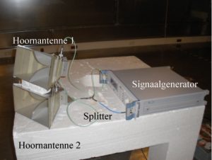
Verification measurements have been carried out with independent intentional radiators which were realized with the help of a set of two horn antennas and signal generators. The actual injected power at the input of the horn antenna was measured beforehand and is called the actual TRP (TRPactual). In Figure 6, the measurement set-up is represented. The average received power (Pavg) is measured with the help of a receive horn antenna and a broadband power meter. After correcting the measured average received power with the appropriate ACF factor, the estimated TRP (TRPestimated) can be calculated (2).
(2) TRPestimated (dBm) = Pavg (dBm) + ACF (dB)
(3) TRPestimated (dBm) – TRPactual (dBm) = Δ
The difference between the estimated TRP and the actual TRP gives an indication of the accuracy with which TRP measurements can be performed in the RvC (3). The noise level of the RvC was determined by performing a TRP measurement on an empty chamber. The measured value of Pavg was found to be -52 dBm. Correcting this value for the worst case ACF (44 dB at 5.5 GHz, Figure 5, Table 3) gives us a conservative minimum value of TRP that can be measured inside this RvC of 0.16 mW (-52 dBm + 44 dB = -8 dBm = 0.16 mW). By applying a pre-amplifier, this noise level could be further reduced to 1 μW which was needed in the case of measuring the TRP of unintentional radiators (Figure 5, Table 4).

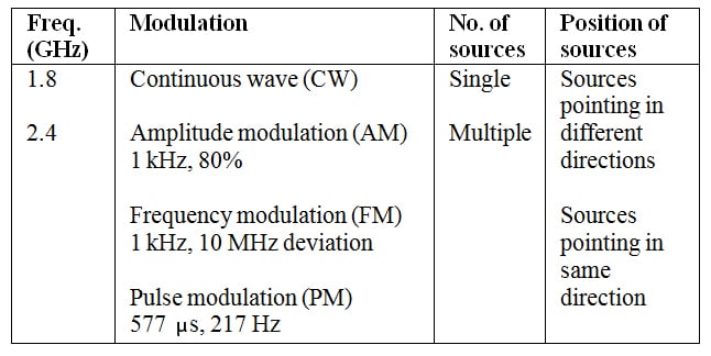
Several verification measurements have been performed in which various combinations of factors such as frequency, modulation, number of sources and positioning of source have been varied to get an optimal set of data (Table 1). Each measurement was carried out three times to get an idea of the repeatability of the measurement method.
In case of a single source, the estimated TRP can be found by simply adding the ACF at that particular frequency to the measured received power. In case of multiple independent sources the TRP is obtained by adding the TRPs of the individual sources [7]. Therefore, for measuring the TRP of multiple sources in the RvC at different frequencies, the estimated TRP is determined by adding the worst case ACF in the frequency range spanning over all sources to the measured received power. Since the worst case ACF is used, the estimated TRP is in fact a very conservative value.
In the case of multiple sources at the same frequency, the estimated TRP can be determined again by simply adding the ACF at the appropriate frequency to the measured received power.
When the sources are modulated, one should be careful in determining the correct chamber calibration factor (ACF) depending upon the frequency span of the spectral components of the modulated signals.
In terms of accuracy it can be said that for a single source, the TRP can be determined with an accuracy of approximately 2 dB (Δ). In the case of multiple sources at different frequencies, the TRP can be determined with an accuracy of 3 dB (Δ). One should keep in mind that in this case a conservative value of TRP is determined since the worst case ACF is used as correction. For multiple sources at one frequency, the TRP can be determined with an accuracy of less than 0.5 dB (Δ).

Table 2 shows the measurement results of one of the verification measurements (multiple sources at one frequency: 2.4 GHz, CW); see Figure 7. It can be seen that there is a good correlation between the actual and estimated TRP (Δ < 0.5 dB).

Overall, it can be concluded that a good correlation exists between the measured received power and the calculated received power which is obtained by simply adding the individual power components. This implies that all power sources inside the RvC can be treated as uncorrelated; which is known to be an intrinsic property of the RvC. Further details can be found in [9].
TRP MEASUREMENTS ON MM PRODUCTS
The block diagram for the TRP measurements is given in Figure 2. The MM product is placed in the middle of the working volume of the RvC (Figure 8). Measurements are carried out in two frequency ranges, namely, 80 – 1000 MHz and 1 – 6 GHz. An additional pre-amplifier is applied to get sufficient dynamic range since power levels emitted from MM products are low.
In general, a product may contain spurious sources of emission (unintentional radiators) as well as one or more wireless technologies (intentional radiators). Power measurements are done over a complete frequency range as opposed to a fixed frequency (as was the case in the verification measurements) meaning that a broadband measurement is performed. For this reason, the worst case ACF per frequency range has to be taken as correction factor (Figure 4, Figure 5 and Table 3). This provides a worst case estimate of the actual TRP.
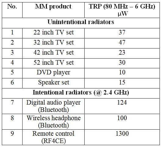
Primarily, TRP measurements were carried out on a range of MM products classified as unintentional radiators, i.e. products which do not contain an antenna to intentionally transmit RF power (e.g. TV set, monitor, DVD player, digital audio player, etc.). The obtained results were analyzed and compared to the TRP-limit of 20 mW (Table 4). It was found that a typical level of TRP for these unintentional radiating MM products is in the order of tens of μW and hence is much smaller than the low-power limit of 20 mW [8].
Additionally, TRP measurements were carried out on MM products having one or more intentional radiators (e.g. wireless headphone, RF4CE remote control) [10]. For proper functioning, auxiliary equipment was needed to obtain the wireless link. The maximum measured TRP level of intentional radiators in which a Bluetooth link was set-up was in the order of 100 – 150 μW. This is much lower than the maximum permitted power of 2.5 mW (Bluetooth 10 m, class 2) as well as the TRP-limit of 20 mW (Table 4). For the RF4CE remote control, a TRP of 1.3 mW was measured which is again much lower than the maximum permitted power of 100 mW (Zigbee RF4CE) as well as the 20 mW TRP-limit. For both Bluetooth and RF4CE it is a known fact that the transmitted power is scaled down after the wireless link is established.
CONCLUSIONS
The low power criterion of 20 mW can be used as a limit to demonstrate EMF compliance of MM products. The RvC proves to be a useful tool in the determination of the TRP of MM products. After performing a relatively quick calibration, the RvC can be used to measure TRP over a time period of 6 minutes. Verification measurements with known sources show a good repeatability of the method. Also a good correlation is found between the actual and estimated TRP for single as well as multiple sources. Measurements carried out on actual MM products show that TRP values lie far below the 20 mW limit for both unintentional as well as intentional radiators.
REFERENCES
[1] IEC 62311 – International Standard – Assessment of electronic and electrical equipment related to human exposure restrictions for electromagnetic fields (0 Hz – 300 GHz), Edition 1, 2007-08.
[2] ECMA International Technical Report – TR/97 – Guide for assessment of human exposure to electromagnetic fields from multimedia products in accordance with IEC/EN 62311, 1st edition, June 2009.
[3] ICNIRP Guidelines for limiting exposure to time-varying electric, magnetic and electromagnetic fields (up to 300 GHz) – International commission on non-ionizing radiation protection, Published in Health Physics 74(4): 494-522; 1998.
[4] IEC 62479 – International Standard – Assessment of the compliance of low-power electronic and electrical equipment with the basic restrictions related to human exposure to electromagnetic fields (10 MHz – 300 GHz), Edition 1, 2010-06.
[5] S. Depienne et al, The reverberation chamber: a useful tool to characterize the radiated power of small RF devices, IEEE conference publications 2003, page(s) 461-464.
[6] IEC 61000-4-21 – International standard – Testing and measurement techniques – Reverberation Chamber test methods, Edition 2, 2011-01.
[7] IEC/TR 62630 – Technical Report – Guidance for evaluating exposure from multiple electromagnetic sources, Edition 1, 2010-03.
[8] ECMA white paper ECMA/TC20/2009/019, Total Radiated Power Measurement Results of Multimedia products in Reverberation Chamber; Unintentional radiators, version 3, 2009-04-06.
[9] Philips EMC Center Report – Total Radiated Power Measurements Reverberation Chamber; Verification of TRP measurements of multiple intentional radiators – EMC-09-KB-005-RRP, Konika Banerjee, 2009-06-16.
[10] Philips EMC Center Report – Total Radiated Power Measurement Results of Multimedia products in Reverberation Chamber – Part 2; Intentional and unintentional radiators – EMC-09-KB-012-RRP, Konika Banerjee, 2009-12-03.


