NOTE: The below article has been translated from Spanish and can be found in its original language in the 2012 EMC Europe Guide.
W.G. Fano, Faculty of Engineering, Universidad de Buenos Aires, Buenos Aires, Argentina
ABSTRACT
Fluorescent lamps, in particular compact fluorescent lamps, are replacing incandescent lamp worldwide. This new technology offers the benefit of lower energy consumption—about five times that of incandescent lamps—but due to the employment of the electronic ballast of high frequency could interfere electronic equipment because of electromagnetic field emissions produced by the electronics and arc mechanism of the lamp, as well as conducted emissions by electrical wires. This article is devoted to the measurement and the study of the radiated emissions characteristics of the CFL at short distances.
INTRODUCTION
Incandescent Lamps
“A traditional incandescent lamp produces light when a tungsten filament carrying a current inside a bulb filled with an inert gas is brought to high temperature by the Joule effect. However, this technology has a low efficiency. Moreover, the lifetime of that lamp is relatively low because the hot filament gradually vaporizes on the walls of the glass, and eventually breaks after a few hundred hours of operation.” [4]
“The filament of an incandescent lamp is simply a resistor that is temperature-dependent, which in turn depends mainly on the filament’s length, thickness and material. If electrical power is applied, it is converted to heat in the filament. The filament’s temperature rises until it gets rid of heat at the same rate that heat is being generated in the filament. Ideally, the filament gets rid of heat only by radiating it away, although a small amount of heat energy is also removed from the filament by thermal conduction. The filament’s temperature is very high, generally over 2,000 degrees Celsius, or generally over 3,600 degrees Fahrenheit. At high temperatures like this, the thermal radiation from the filament includes a significant amount of visible light. The poor efficiency is the fact that tungsten filaments radiate mostly infrared radiation at any temperature that they can withstand.” [7]

Incandescent lamps radiate at frequency of 50/60Hz, depending on the country, because of the current supplied to the filament. This radiation will be masked by the radiation produced by the transmission lines of the energy distribution of the city.
Fluorescent Lights
“There are a wide variety of non-incandescent visible light sources that are employed for indoor and outdoor lighting. Most of these light sources are based on electric discharge through a gas such as mercury, or the Noble gases neon, argon and xenon. The generation of visible light in gas discharge lamps relies on collisions between atoms and ions in the gas with an electrical current that is passed between a pair of electrodes placed at the ends of the bulb envelope.” [8]

“The glass tube of a common fluorescent lamp is coated with phosphor on the inside surface of the glass, and the tube is filled with mercury vapor at very low pressure (see Figure 2). An electric current is applied between the electrodes at the ends of the tube, producing a stream of electrons that flow from one electrode to the other. When electrons from the stream collide with mercury atoms, they excite electrons within the atoms to a higher energy state. This energy is released in the form of ultraviolet radiation when electrons in the mercury atoms return to the ground state. The ultraviolet radiation subsequently energizes the internal phosphor coating, causing it to emit the bright white light that we observe from fluorescent lights. Fluorescent lamps are about two to four times more efficient at emitting visible light, produce less waste heat, and typically last ten to twenty times longer than incandescent lamps.” [8]
“A unique feature of fluorescent light sources is that they generate a series of wavelengths that are often concentrated into narrow bands termed line spectra. As a consequence, these sources do not produce the continuous spectrum of illumination that is characteristic of incandescent sources. It is possible to design gas-discharge lamps that will emit a nearly continuous spectrum in addition to the line spectra inherent in most of these lamps. The most common technique is to coat the inside surface of the tube with phosphor particles, which will absorb radiation emitted by the glowing gas and convert it into a broad spectrum of visible light ranging from blue to red.” [8]

CFL History
“The helical compact fluorescent lamp was invented by Ed Hammer at GE in 1976. His proposal was to coil a long, thin high efficiency tube into this form, such that it would better match the size and light distribution of a frosted incandescent lamp. However, GE felt that coiling glass tubes into this complex shape was not compatible with high speed manufacturing techniques, and the idea was shelved [1][2].
It was not until 1992 that GE completed a machine for bending the glass, and samples of the so-called Heliax lamp that it produced were issued to the market that year. Sadly the lamp never made it to mass production, owing to extreme difficulty in controlling the production process.” [1][2]
“The commercial introduction of the lamp had to wait a further three years until a Chinese firm, Shanghai Xiangshan, marketed the first successful design. This is Phillips’ first lamp from 2003.” [1]
Fluorescent Lamp: An Overview
The fluorescent lamps has been used in office and other commercial environments, giving light at an efficiency of 5-10 times that of standard tungsten filament bulbs. The fluorescent tube contains an electrode with a gas fill of typically an argon/krypton mix and a small amount of mercury. It is a discharge lamp; the discharge is initiated by a starter and after that controlled by a ballast, which is traditionally an iron cored inductor. When the arc has been struck, the ballast schemes the current flowing and the circuit operates at mains supply frequency. When the operation is normal, radio frequency emissions from a mains frequency fluorescent lamp occur because of arcing at the electrodes. [9]
The operation of a fluorescent lamp at higher frequency leads to a reduction in detectable visual flicker, a reduction in audio ‘hum’, increased ease of dimming and an increase in efficiency of up to approximately 25%. For that reason higher frequency operation is desirable so as to meet the requirements, using electronic switching ballast. [5]

Why is the Compact Fluorescent Lamp (CFL) used? In Figure 4 a picture of a CFL can be observed. The most important reason why the CFL is used is the electrical consumption. This can be showed in the Figure 5, where the CFL has a consumption about five times compared with that the incandescent type.

MAGNETIC FIELD MEASUREMENT
A well known method to measuring the Magnetic Field (Hi) of electromagnetic wave propagation is using a loop, or loop antenna, that can be observed in Figure 6.
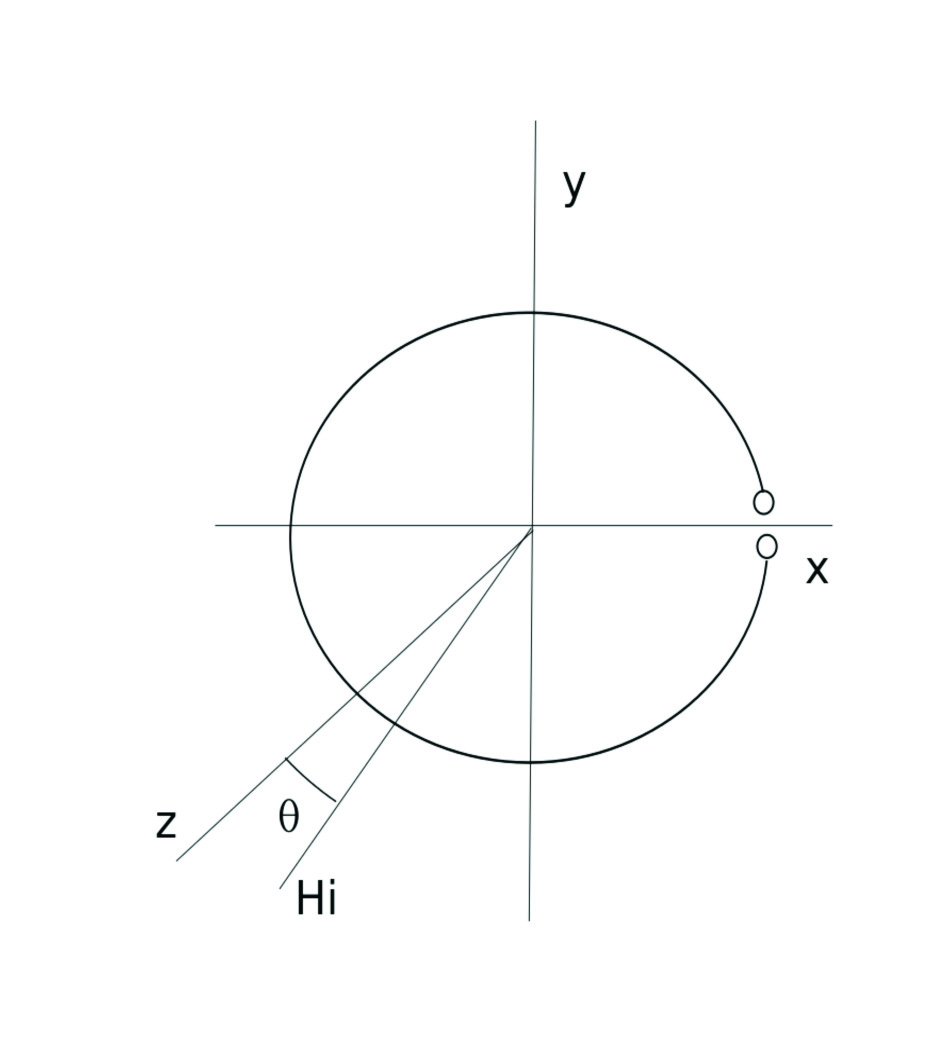
The induced voltage in the loop at the open circuit can be obtained using of Faraday Law [6] , allowing for the voltage to be written thus:
where:
n is the number of turns;
w: is the angular pulsation;
A: is the area of the loop; and
q: is the angle between z and Hi.
More details about the antenna parameters to perform a H field measurement are described in the Appendix.
EXPERIMENTAL
The loop antenna of air has been designed with a dielectric cylinder with a wire on it, with:
Loop diameter = 0.1m, 50 turns, and Wire section = 0.5mm2
It is interesting to note that the Voltage Voc from equation 1 increases with the area and the number of turns (n)–this can be used to select an adequate voltage. The wire section has been chosen to reduce the resistance losses of the wire. As the device is essentially an inductor, in practice the resistance with this loop antenna can be neglected compare with the reactance. In the Figure 7, the construction of the loop antenna is depicted.
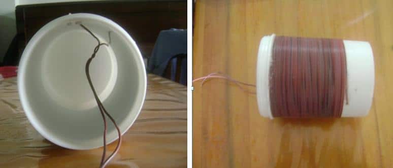
In order to observe the emissions of the RF radiations of the CFL, the magnetic field produced by the CFL has been measured as a function of the distance of the CFL. There are two possibilities of H field measurement: in the axis direction of the loop and the radial direction of the Loop, as can be observed in Figures 8 and 9.


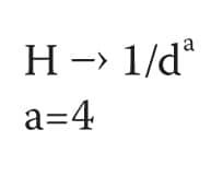
The magnetic field measured of the Osram brand CFL with 11W of power and connected to 220V/50Hz in the axial and radial direction can be observed in Figure 10 and 11. This Magnetic Field have been also modeled as a function of the distance “d” with an exponent a. Thus:


It is interesting to observe that usually in linear antennas like thin dipole antennas, the magnetic field near the antenna have a reactive region and a dependence with the distance of 1/d3; this is usually for the antenna community [6]. In this paper, the dependence of the Magnetic Field has been measured as 1/d4 .This means that the Magnetic Field of CFL is decreasing faster than thin dipole antennas.
The magnetic field measured in the radial direction from Figure 11 is about six times lower compared to the magnetic field in the axial magnetic field from Figure 10.
CONCLUSIONS
The magnetic field levels of compact fluorescent lamps have been measured, and the more important levels have been detected between 40 and 50kHz in the axial direction. The levels in the radial direction are six times lower than axial direction, and could be neglected.
In the frequency of 150kHz, the received power are considerable lower compare with the 40-50kHz band.
As an interference test, you can locate an AM receiver at Medium Frequency near the CFL and the reception will be interfered with an audible noise that you can hear.

The CFL generate an electromagnetic field in the 40-50kHz bandwidth, which can interfere with other electronic circuits; these emissions are in the near field due to the band of frequencies. If the room has some electronic devices that are sensitive to these magnetic fields, it is desirable to replace the CFL with another type of light, such as LED connected to a voltage regulator employing a linear regulator with no switching power. The incandescent lights can be used as well because they don’t have emissions.

INSTRUMENTATION
Spectrum Analyzer PSA 6000 9 kHz – 6.2GHz
Vector Impedance Meter HP4815
AEA Impedance Analyzer 200kHz – 200MHz
Instek LCR 1kHz- 100kHz
APPENDIX
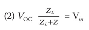
The electrical circuit of a n turns Loop as a receiving antenna is represented by the impedance Z=R+jX in series with a voltage generator. The spectrum analyzer is represented by an impedance of 50 Ω. This electrical circuit can be observed in Figure 12, where: Voc: Voltage of the open circuit; ZL: Load impedance of the spectrum analyzer; and Z is the impedance of the loop antenna.
The measured voltage in the spectrum analyzer can be written thus:
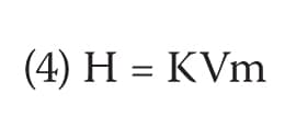
From Equations 1 and 2, the magnetic field can be expressed as a function of voltage Vm:
From Equation 3, the antenna factor can be defined as the relation between the magentic field and the induced voltage in the loop as follows:
and then antenna factor is:
This factor is very important because it relates the measured voltage with the magnetic field vector, which is the unknown.

In Figure 14, the picture of the impedance measurement set up of the loop antenna is shown. The results of the measurement of the reactance as a function of the frequency of the loop antenna can be observed in Figure 15, where the reactance is linear and increasing with the frequency. This represent an inductive behaviour.
In Figure 15, the reactance is linear up to 1,700 kHz, and then the reactance is away from the linear response. This is due the proximity of the frequency of resonance of the antenna because the coil has stray capacitance, and thus the frequency of resonance will decrease as the number of turns increase.
Figure 16 shows the antenna factor of Equation 5. This factor is used to obtain the magnetic field measured.


REFERENCES
1) ^ “Philips Tornado Asian Compact Fluorescent”. Philips. Retrieved 2007-12-24.
2) ^ “Compact Fluorescent Light Bulbs”. Energy Star. Retrieved 2010-09-30.
3) Antenna Engineering Handbook. 3rd Ed. R.C. Jhonson. Mac-Graw Hill Inc. 1993.
4) Characterization of compact fluorescent lights RF emissions in the perspective of human exposure. T. Letertre, A. Azoulay, A. Destrez, F. Gaudaire y Christophe Martinsons. EMC’09/ Kyoto.
5) http://www.ofcom.org.uk/static/archive/ra/topics/research/topics/emc/8056cr2.pdf
6) Antenna Theory Analysis and Design 2nd Ed. C.A. Balanis. J. Wiley. 1997.
7) The Great Internet Light Bulb Book, Part I. Donald L. Klipstein. http://freespace.virgin.net/tom.baldwin/bulbguide.html
8) http://micro.magnet.fsu.edu/primer/lightandcolor/lightsourcesintro.html


